Topic 7: Momentum, Kinetic Energy and Rigid Body Dynamics - Problem Sets

Source: sources/cuatrimestre-1/03-engineering-mechanics/problemas/Problems.pdf (2026 Edition)
Statements and solutions: These are the rigid body problems of Problems.pdf section 2, solved in the lecturer's order: frames, bases and degrees of freedom; change of basis, position vectors and constraint kinematics; centre of mass and inertia tensor; momentum and energy; free-body diagram and equations of motion; answers and checks.

Linear momentum, angular momentum and kinetic energy

Problem RB 06

Blade Runner (Spinner)

Original statement · Problems.pdf, p. 40
Group C: Momentum and EnergyIn-Class Session 19

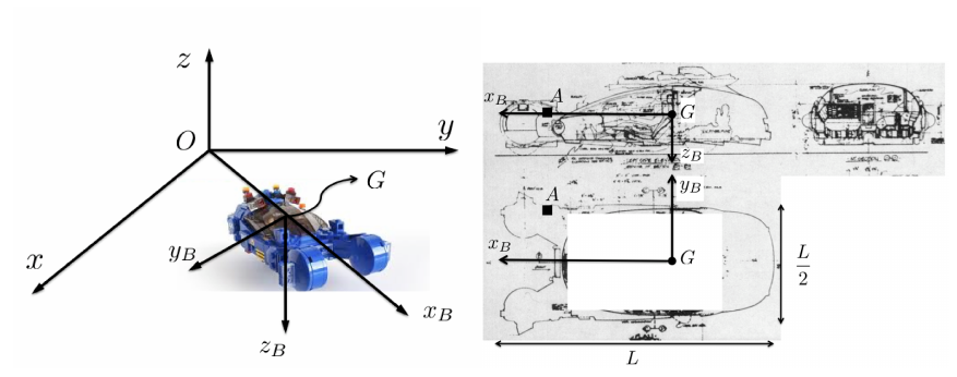
Los Angeles 2019. Deckard is a special policeman (a blade runner) specialized in “retiring” Nexus 6 replicants. He goes around in a spinner, his flying car. We want to analyze the flying motion of the spinner with respect to an inertial reference frame $S_0 : \{O; B_0\}$ with $B_0 : \{\mathbf{i}, \mathbf{j}, \mathbf{k}\}$ as shown in the figure. We are going to consider the spinner as a rigid body. A body-fixed reference frame $S_B : \{G; B_B\}$ with $B_B : \{\mathbf{i}_B, \mathbf{j}_B, \mathbf{k}_B\}$ is also defined. In the instant considered,

  • the center of mass $G$ and the axes $Gx_B$ and $Gy_B$ are contained in the plane $Oxy$,
  • the distance between $G$ and $O$ is $3L/2$, where $L$ is the length of the spinner as indicated in the figure,
  • the angle between the axis $Ox$ and $Gx_B$ is $45^\circ$
  • the velocity of $G$ is $\boldsymbol{v}_0^G = 3\sqrt{2}\Omega L(-\boldsymbol{i} + \boldsymbol{j})/4$,
  • the velocity of point $A$ of the body is $\boldsymbol{v}_0^A = \Omega L(\boldsymbol{i}_B - 8\boldsymbol{j}_B + \sqrt{2}\boldsymbol{k}_B)/4$, where the position vector of $A$ is given by $\boldsymbol{r}_B^A = (2\boldsymbol{i}_B + \boldsymbol{j}_B)L/4$,
  • we also know that $\boldsymbol{v}_0^G \cdot \boldsymbol{\omega}_{B0} = 0$, where $\boldsymbol{\omega}_{B0}$ is the angular velocity of the spinner.

The mass of the spinner is $M$. The inertia tensor about $G$ is

$$ \overline{\overline{I}}_G = ML^2 \begin{bmatrix} B & 0 & E \\ 0 & C & F \\ E & F & D \end{bmatrix}_b , $$

where $B$, $C$, $D$, $E$ and $F$ are known constants. Compute

Spinner with the inertial frame $S_0$ (axes $x$, $y$, $z$, origin $O$) and the body frame $S_B$ (axes $x_B$, $y_B$, $z_B$, origin $G$) in an oblique view, and its top and side views with the points $G$ and $A$ and the dimensions $L$ and $L/2$.
Figure: Spinner with the inertial frame $S_0$ (axes $x$, $y$, $z$, origin $O$) and the body frame $S_B$ (axes $x_B$, $y_B$, $z_B$, origin $G$) in an oblique view, and its top and side views with the points $G$ and $A$ and the dimensions $L$ and $L/2$. (Problems.pdf, p. 40).
Worked Solution [ Click to Expand ]

Reference Frames, Bases and Degrees of Freedom

  • Physical system: the spinner, one rigid body $b$ of mass $M$, observed at a single instant from an inertial frame.
  • Fixed frame: $S_0\{O; \mathcal B_0\}$ with the right-handed basis $\{\mathbf i, \mathbf j, \mathbf k\}$; read from the figure, $\mathbf k$ points up, $\mathbf j$ to the right and $\mathbf i$ towards the viewer.
  • Body frame: $S_B\{G; \mathcal B_B\}$ with origin at the centre of mass $G$ and basis $\{\mathbf i_B, \mathbf j_B, \mathbf k_B\}$. Read from the figure: $\mathbf k_B$ points vertically down (the side view draws it from $G$ downwards), $\mathbf i_B$ lies in the plane $Oxy$ at 45 degrees from $Ox$ and points to the front of the car, and $\mathbf j_B$ completes the right-handed triad.
  • Degrees of freedom: a free rigid body has six (three for the position of $G$, three for the attitude). The problem is a snapshot: the velocity field at this instant is fixed by six scalars, the velocity of $G$ and the angular velocity $\boldsymbol\omega_{B0}$ (Notes.pdf, Sec. 9.1.3).
  • Basis of work: every vector is written in $\mathcal B_B$, because the inertia tensor and the data of $A$ are given there.
DatumValueSI unit
Mass of the spinner$M$kg
Length of the spinner$L$m
Angular rate scale$\Omega$rad/s
Distance $OG$$3L/2$, with $G$ in the plane $Oxy$m
Angle from $Ox$ to $Gx_B$$45^\circ$, with $Gx_B$ and $Gy_B$ in the plane $Oxy$rad
Velocity of $G$$\mathbf v_0^G = \tfrac{3\sqrt2}{4}\,\Omega L\,(-\mathbf i + \mathbf j)$m/s
Position of $A$ from $G$$\mathbf r_G^A = \tfrac{L}{4}\,(2\,\mathbf i_B + \mathbf j_B)$m
Velocity of $A$$\mathbf v_0^A = \tfrac{\Omega L}{4}\,(\mathbf i_B - 8\,\mathbf j_B + \sqrt2\,\mathbf k_B)$m/s
Extra condition$\mathbf v_0^G\cdot\boldsymbol\omega_{B0} = 0$m rad/s$^2$
Inertia tensor about $G$ in $\mathcal B_B$$ML^2\,[B, 0, E;\ 0, C, F;\ E, F, D]$, constants $B$, $C$, $D$, $E$, $F$kg m$^2$
  • Unknowns: the three components of $\boldsymbol\omega_{B0}$, a point $I$ of the instantaneous axis of rotation, the kinetic energy $T_0$, and the angular momenta $\mathbf H_{G,0}$ and $\mathbf H_{A,0}$.
  • Count of equations: the velocity field between $G$ and $A$ gives three scalar equations, but its component along the segment $GA$ contains no angular velocity (it is a consistency check of the data). The other two fix two components of $\boldsymbol\omega_{B0}$; the condition on the scalar product fixes the third.
  • Datum not used: the distance $OG$ is not needed, because every quantity asked for is referred to $G$ or $A$, and the axis of rotation is located from $G$.

Change of Basis, Position Vectors and Constraint Kinematics

The basis $\mathcal B_B$ is reached from $\mathcal B_0$ by two simple rotations: a turn of 45 degrees about $\mathbf k$ (it brings an intermediate axis $\mathbf i_1$ onto the direction of $Gx_B$) and a half turn about $\mathbf i_1$ (it sends the vertical axis downwards, as the figure draws $\mathbf k_B$).

Two simple rotations

i j i1 j1 cos 45° sin 45° −sin 45° cos 45° 45° 45° k (⊙)
Figure 1. First simple rotation, by $45^\circ$ about $\mathbf k$ (⊙). The axis $\mathbf i_1$ takes the direction of the length of the spinner; $\mathbf j_1$ leans to negative $\mathbf i$, which gives the minus sign of $[{}_0R_1]$.
First rotation: 45 degrees about k Law: simple rotation about the third axis, positive by the right-hand rule Source: Notes.pdf, Eq. 1.20; Notes.pdf, Eq. 1.15; [Lecture 7, Slide 12]

View from above, with $\mathbf k$ out of the paper (⊙), $\mathbf i$ to the right and $\mathbf j$ up, since $\mathbf i\times\mathbf j = \mathbf k$. The turn from $Ox$ to $Gx_B$ is counterclockwise in this view, so its angle is positive.

$$\begin{aligned} \mathbf i_1 &= \cos 45^\circ\,\mathbf i + \sin 45^\circ\,\mathbf j \quad &\text{(right triangle with hypotenuse 1: adjacent leg along $\mathbf i$, opposite leg along $\mathbf j$)} \\ \mathbf j_1 &= -\sin 45^\circ\,\mathbf i + \cos 45^\circ\,\mathbf j \quad &\text{($\mathbf j$ turned counterclockwise about $\mathbf k$, out of the paper, leans to the left: negative $\mathbf i$ leg)} \\ \mathbf k_1 &= \mathbf k \quad &\text{(the rotation axis does not move)} \\ [{}_0R_1] &= \frac{1}{\sqrt2}\begin{bmatrix} 1 & -1 & 0 \cr 1 & 1 & 0 \cr 0 & 0 & \sqrt2 \end{bmatrix} \quad &\text{(columns: $\mathbf i_1$, $\mathbf j_1$, $\mathbf k_1$ in $\mathcal B_0$; $\cos 45^\circ$ and $\sin 45^\circ$ are $1/\sqrt2$)} \\ \det[{}_0R_1] &= 1\cdot\left(\tfrac{1}{\sqrt2}\cdot\tfrac{1}{\sqrt2} - \left(-\tfrac{1}{\sqrt2}\right)\tfrac{1}{\sqrt2}\right) = 1 \quad &\text{(expand along the third row)} \\ [{}_0R_1][{}_0R_1]^T &= \frac12\begin{bmatrix} 1 + 1 & 1 - 1 & 0 \cr 1 - 1 & 1 + 1 & 0 \cr 0 & 0 & 2 \end{bmatrix} = [U] \quad &\text{(row by row products)} \end{aligned}$$
$$\boxed{\mathbf i_1 = \frac{\mathbf i + \mathbf j}{\sqrt2}, \qquad \mathbf j_1 = \frac{-\mathbf i + \mathbf j}{\sqrt2}, \qquad \mathbf k_1 = \mathbf k}$$

Units: dimensionless

Meaning: the intermediate axis $\mathbf i_1$ points along the length of the spinner, as $Gx_B$ does in the figure; the vertical has not moved yet.

j1 k1 = k jB kB π π i1 = iB
Figure 2. Second simple rotation, a half turn about $\mathbf i_1$ (⊙): $\mathbf j_B$ is opposite to $\mathbf j_1$ and $\mathbf k_B$ points to the ground, as in the side view of the statement.
Second rotation: half turn about i1 Law: simple rotation about the first axis by the angle pi; chaining of two changes of basis Source: Notes.pdf, Eq. 1.18; Notes.pdf, Eq. 1.16; Notes.pdf, Eq. 1.15; [Lecture 7, Slide 12]

View with $\mathbf i_1$ out of the paper (⊙), $\mathbf j_1$ to the right and $\mathbf k_1$ up, since $\mathbf j_1\times\mathbf k_1 = \mathbf i_1$. A half turn sends both axes of the plane of the view to their opposites.

$$\begin{aligned} \mathbf i_B &= \mathbf i_1 \quad &\text{(the rotation axis does not move)} \\ \mathbf j_B &= \cos\pi\,\mathbf j_1 + \sin\pi\,\mathbf k_1 = -\mathbf j_1 \quad &\text{(simple rotation about $\mathbf i_1$ with angle $\pi$: cosine $-1$, sine $0$)} \\ \mathbf k_B &= -\sin\pi\,\mathbf j_1 + \cos\pi\,\mathbf k_1 = -\mathbf k \quad &\text{(same rotation; the vertical axis now points down)} \\ [{}_1R_B] &= \begin{bmatrix} 1 & 0 & 0 \cr 0 & -1 & 0 \cr 0 & 0 & -1 \end{bmatrix} \quad &\text{(columns: $\mathbf i_B$, $\mathbf j_B$, $\mathbf k_B$ in $\mathcal B_1$)} \\ [{}_0R_B] &= [{}_0R_1]\,[{}_1R_B] = \frac{1}{\sqrt2}\begin{bmatrix} 1 & 1 & 0 \cr 1 & -1 & 0 \cr 0 & 0 & -\sqrt2 \end{bmatrix} \quad &\text{(chaining: the second and third columns of the first matrix change sign)} \\ \det[{}_0R_B] &= (-1)\cdot\frac12\,\left(1\cdot(-1) - 1\cdot 1\right) = 1 \quad &\text{(expand along the third row: the entry $-1$ times the minor $-1$)} \\ [{}_0R_B][{}_0R_B]^T &= \frac12\begin{bmatrix} 1 + 1 & 1 - 1 & 0 \cr 1 - 1 & 1 + 1 & 0 \cr 0 & 0 & 2 \end{bmatrix} = [U] \quad &\text{(row by row products)} \end{aligned}$$
$$\boxed{\mathbf i_B = \frac{\mathbf i + \mathbf j}{\sqrt2}, \qquad \mathbf j_B = \frac{\mathbf i - \mathbf j}{\sqrt2}, \qquad \mathbf k_B = -\mathbf k}$$

Units: dimensionless

Meaning: the body basis has $\mathbf i_B$ along the car, $\mathbf j_B$ horizontal across it, and $\mathbf k_B$ pointing to the ground. The determinant 1 confirms that the triad read from the figure is right-handed.

Velocity of G in the body basis

Velocity of G in the body basis Law: components of a vector in another basis, with the inverse matrix equal to the transpose Source: Notes.pdf, Eq. 1.12; Notes.pdf, Eq. 1.14
$$\begin{aligned} [\mathbf v_0^G]_B &= [{}_0R_B]^T\,[\mathbf v_0^G]_0 \quad &\text{(the transpose takes components from $\mathcal B_0$ to $\mathcal B_B$)} \\ &= \frac{1}{\sqrt2}\begin{bmatrix} 1 & 1 & 0 \cr 1 & -1 & 0 \cr 0 & 0 & -\sqrt2 \end{bmatrix}\frac{3\sqrt2\,\Omega L}{4}\begin{bmatrix} -1 \cr 1 \cr 0 \end{bmatrix} \quad &\text{(the matrix is symmetric, so it equals its transpose; data of the statement)} \\ &= \frac{3\,\Omega L}{4}\begin{bmatrix} -1 + 1 \cr -1 - 1 \cr 0 \end{bmatrix} \quad &\text{(row by column products; the two square roots cancel)} \\ &= \frac{3\,\Omega L}{4}\begin{bmatrix} 0 \cr -2 \cr 0 \end{bmatrix} \quad &\text{(add)} \end{aligned}$$
$$\boxed{\mathbf v_0^G = -\frac{3}{2}\,\Omega L\,\mathbf j_B}$$

Units: $[\mathrm{T^{-1}}][\mathrm L] = [\mathrm{L\,T^{-1}}]$

Meaning: at this instant the centre of mass moves sideways, perpendicular to the length of the car, with speed 1.5 times the product of the rate and the length.

Angular velocity from the velocity field

Two components of the angular velocity from the velocity field Law: velocity field of a rigid body between two body points; vector product by its determinant Source: Notes.pdf, Eq. 9.3; Notes.pdf, Eq. 9.7; Notes.pdf, Eq. 1.31; [Lecture 7, Slide 6]

Write the unknown angular velocity as $\boldsymbol\omega_{B0} = p\,\mathbf i_B + q\,\mathbf j_B + r\,\mathbf k_B$.

$$\begin{aligned} \mathbf v_0^A - \mathbf v_0^G &= \boldsymbol\omega_{B0}\times\mathbf r_G^A \quad &\text{(velocity field from $G$ to $A$, Eq. 9.3)} \\ \mathbf v_0^A - \mathbf v_0^G &= \frac{\Omega L}{4}\left(\mathbf i_B - 8\,\mathbf j_B + \sqrt2\,\mathbf k_B\right) + \frac{6\,\Omega L}{4}\,\mathbf j_B \quad &\text{(data; minus the velocity of $G$ of the previous box)} \\ &= \frac{\Omega L}{4}\left(\mathbf i_B - 2\,\mathbf j_B + \sqrt2\,\mathbf k_B\right) \quad &\text{(collect the $\mathbf j_B$ terms)} \\ \boldsymbol\omega_{B0}\times\mathbf r_G^A &= \frac{L}{4}\begin{vmatrix} \mathbf i_B & \mathbf j_B & \mathbf k_B \cr p & q & r \cr 2 & 1 & 0 \end{vmatrix} \quad &\text{(determinant form, with the factor $L/4$ taken out)} \\ &= \frac{L}{4}\left[\mathbf i_B\,(q\cdot 0 - r\cdot 1) - \mathbf j_B\,(p\cdot 0 - r\cdot 2) + \mathbf k_B\,(p\cdot 1 - q\cdot 2)\right] \quad &\text{(expand along the first row)} \\ &= \frac{L}{4}\left[-r\,\mathbf i_B + 2r\,\mathbf j_B + (p - 2q)\,\mathbf k_B\right] \quad &\text{(carry out the products)} \\ -r &= \Omega \quad &\text{(equate the $\mathbf i_B$ components, after cancelling $L/4$)} \\ 2r &= -2\,\Omega \quad &\text{(equate the $\mathbf j_B$ components: the same condition, a check of the data)} \\ p - 2q &= \sqrt2\,\Omega \quad &\text{(equate the $\mathbf k_B$ components)} \end{aligned}$$
$$\boxed{r = -\Omega, \qquad p - 2q = \sqrt2\,\Omega}$$

Units: $[\mathrm{L\,T^{-1}}] = [\mathrm{T^{-1}}][\mathrm L]$, so $p$, $q$, $r$ are in $[\mathrm{T^{-1}}]$

Meaning: the $\mathbf j_B$ equation repeats the $\mathbf i_B$ one because the two velocities have equal projections on the segment $GA$ (Eq. 9.7): the data are those of a rigid body. A rotation about $GA$ itself moves neither point, so one more condition is needed.

Third component from the condition on the velocity of G Law: scalar product in an orthonormal basis; the condition given in the statement Source: Notes.pdf, Eq. 9.5; Notes.pdf, Eq. 1.40; Problems.pdf, p. 40
$$\begin{aligned} \mathbf v_0^G\cdot\boldsymbol\omega_{B0} &= 0 \quad &\text{(statement)} \\ \left(-\tfrac32\,\Omega L\right) q &= 0 \quad &\text{(only the $\mathbf j_B$ component of the velocity of $G$ is non-zero)} \\ q &= 0 \quad &\text{(the factor in brackets is not zero)} \\ p &= \sqrt2\,\Omega + 2q = \sqrt2\,\Omega \quad &\text{(previous box)} \\ \omega_{B0}^2 &= \left(\sqrt2\,\Omega\right)^2 + 0^2 + (-\Omega)^2 = 3\,\Omega^2 \quad &\text{(squared modulus: sum of the squared components)} \end{aligned}$$
$$\boxed{\boldsymbol\omega_{B0} = \Omega\left(\sqrt2\,\mathbf i_B - \mathbf k_B\right), \qquad \omega_{B0} = \sqrt3\,\Omega}$$

Units: $[\mathrm{T^{-1}}]$

Meaning: the condition says that the slip velocity (the component of the velocity of any body point along the angular velocity, Eq. 9.5) is zero: the spinner is in pure rotation at this instant. It turns about an axis in the vertical plane that contains its length.

Instantaneous axis of rotation

iB kB jB IAR L/2 √2 L/2 GI v0G ωB0 A G I
Figure 3. Instantaneous axis of rotation of the spinner. $I$ is the foot of the perpendicular from $G$; the axis is parallel to $\boldsymbol\omega_{B0}$ and lies in the vertical plane of the car.
A point of the instantaneous axis of rotation Law: the point $I$ of the axis closest to $G$; double vector product Source: Notes.pdf, Eq. 9.8; Notes.pdf, Eq. 9.10; Notes.pdf, Eq. 1.37; [Lecture 7, Slide 9]
$$\begin{aligned} \mathbf{GI} &= \frac{\boldsymbol\omega_{B0}\times\mathbf v_0^G}{\omega_{B0}^2} \quad &\text{(Eq. 9.10 from $G$: foot of the perpendicular from $G$ to the axis)} \\ \boldsymbol\omega_{B0}\times\mathbf v_0^G &= \Omega\cdot\Omega L\begin{vmatrix} \mathbf i_B & \mathbf j_B & \mathbf k_B \cr \sqrt2 & 0 & -1 \cr 0 & -\tfrac32 & 0 \end{vmatrix} \quad &\text{(determinant form, factors taken out)} \\ &= \Omega^2 L\left[\mathbf i_B\left(0\cdot 0 - (-1)\left(-\tfrac32\right)\right) - \mathbf j_B\,(\sqrt2\cdot 0 - (-1)\cdot 0) + \mathbf k_B\left(\sqrt2\left(-\tfrac32\right) - 0\cdot 0\right)\right] \quad &\text{(expand along the first row)} \\ &= \Omega^2 L\left(-\tfrac32\,\mathbf i_B - \tfrac{3\sqrt2}{2}\,\mathbf k_B\right) \quad &\text{(carry out the products)} \\ \mathbf{GI} &= \frac{\Omega^2 L}{3\,\Omega^2}\left(-\tfrac32\,\mathbf i_B - \tfrac{3\sqrt2}{2}\,\mathbf k_B\right) \quad &\text{(divide by the squared modulus $3\Omega^2$)} \\ &= -\frac{L}{2}\left(\mathbf i_B + \sqrt2\,\mathbf k_B\right) \quad &\text{(simplify)} \end{aligned}$$
$$\boxed{\mathbf{GI} = -\frac{L}{2}\left(\mathbf i_B + \sqrt2\,\mathbf k_B\right), \qquad \text{axis: } \mathbf r_G^P = \mathbf{GI} + \lambda\left(\sqrt2\,\mathbf i_B - \mathbf k_B\right)}$$

Units: $[\mathrm{T^{-1}}][\mathrm{L\,T^{-1}}]/[\mathrm{T^{-2}}] = [\mathrm L]$; the parameter $\lambda$ is a length

Meaning: $\mathbf{GI}$ is perpendicular to the angular velocity (its scalar product with it is $-\sqrt2 + \sqrt2 = 0$). Since $\mathbf k_B$ points down, $-\mathbf k_B$ points up: the axis passes behind and above $G$, at a distance of $\sqrt3\,L/2$ from it, in the vertical plane of the car.

Center of Mass and Inertia Tensor

The centre of mass $G$ is the origin of $S_B$, and the inertia tensor about it is a datum of the statement: the mass distribution of the spinner is not given, so no integral can be written. The box below only reads the given matrix with the definitions of the course, which identifies each constant.

Reading the given inertia tensor Law: matrix of the tensor of inertia: moments of inertia on the diagonal, products of inertia with a minus sign off the diagonal Source: Notes.pdf, Eq. 10.38; Notes.pdf, Eq. 10.11; Notes.pdf, Eq. 10.15; [Lecture 8, Slide 12]
$$\begin{aligned} [\bar{\bar I}_G]_{BB} &= \begin{bmatrix} I_{x_B} & -P_{x_Bz_B,y_Bz_B} & -P_{x_By_B,y_Bz_B} \cr -P_{x_Bz_B,y_Bz_B} & I_{y_B} & -P_{x_By_B,x_Bz_B} \cr -P_{x_By_B,y_Bz_B} & -P_{x_By_B,x_Bz_B} & I_{z_B} \end{bmatrix} \quad &\text{(Eq. 10.38 in the body basis)} \\ I_{x_B} &= B\,ML^2, \quad I_{y_B} = C\,ML^2, \quad I_{z_B} = D\,ML^2 \quad &\text{(compare the diagonals)} \\ P_{x_Bz_B,y_Bz_B} &= 0, \quad P_{x_By_B,y_Bz_B} = -E\,ML^2, \quad P_{x_By_B,x_Bz_B} = -F\,ML^2 \quad &\text{(compare the off-diagonal entries)} \end{aligned}$$
$$\boxed{\bar{\bar I}_G = ML^2\begin{bmatrix} B & 0 & E \cr 0 & C & F \cr E & F & D \end{bmatrix}_{BB}}$$

Units: $[\mathrm M][\mathrm L^2]$ (kg m$^2$); $B$ to $F$ are pure numbers

Meaning: the zero product means that the integral of the product of the coordinates along $\mathbf i_B$ and $\mathbf j_B$ over the car vanishes; the axes of $S_B$ are not principal axes, because $E$ and $F$ couple the vertical axis with the other two.

Linear Momentum, Angular Momentum and Kinetic Energy

Linear momentum Law: linear momentum of a rigid body equals the mass times the velocity of the centre of mass Source: Notes.pdf, Eq. 11.3; [Lecture 9, Slide 3]
$$\begin{aligned} \mathbf p_0 &= \int_{\mathcal D}\mathbf v_0^P\,dm = M\,\mathbf v_0^G \quad &\text{(definition, Eq. 11.1, reduced by Eq. 11.3)} \\ &= -\frac32\,M\Omega L\,\mathbf j_B \quad &\text{(velocity of $G$ in $\mathcal B_B$)} \end{aligned}$$
$$\boxed{\mathbf p_0 = -\frac32\,M\Omega L\,\mathbf j_B}$$

Units: $[\mathrm M][\mathrm{L\,T^{-1}}]$ (kg m/s)

Meaning: the momentum is that of a particle of mass $M$ moving with $G$; it is needed for the change of pole from $G$ to $A$.

Angular momentum about G Law: angular momentum about the centre of mass equals the inertia tensor about $G$ applied to the angular velocity Source: Notes.pdf, Eq. 11.12; Notes.pdf, Eq. 11.19; [Lecture 9, Slide 5]
$$\begin{aligned} \mathbf H_{G,0} &= \bar{\bar I}_G\cdot\boldsymbol\omega_{B0} \quad &\text{(Eq. 11.12 with $A$ at $G$; the same in $S_0$ and in $S_G$, Eq. 11.19)} \\ [\mathbf H_{G,0}]_B &= ML^2\begin{bmatrix} B & 0 & E \cr 0 & C & F \cr E & F & D \end{bmatrix}\Omega\begin{bmatrix} \sqrt2 \cr 0 \cr -1 \end{bmatrix} \quad &\text{(matrices in $\mathcal B_B$)} \\ &= ML^2\Omega\begin{bmatrix} \sqrt2\,B + 0 - E \cr 0 + 0 - F \cr \sqrt2\,E + 0 - D \end{bmatrix} \quad &\text{(row by column products)} \end{aligned}$$
$$\boxed{\mathbf H_{G,0} = M\Omega L^2\left[\left(\sqrt2\,B - E\right)\mathbf i_B - F\,\mathbf j_B + \left(\sqrt2\,E - D\right)\mathbf k_B\right]}$$

Units: $[\mathrm M][\mathrm L^2][\mathrm{T^{-1}}]$ (kg m$^2$/s)

Meaning: the angular momentum is not parallel to the angular velocity: the products of inertia $E$ and $F$ add components along $\mathbf j_B$ and change the ratio of the other two.

Kinetic energy by Koenig's decomposition Law: kinetic energy of a rigid body: translation of $G$ plus rotation about $G$ Source: Notes.pdf, Eq. 11.31; Notes.pdf, Eq. 11.37; [Lecture 9, Slide 10]
$$\begin{aligned} T_0 &= \frac12\,M\left(v_0^G\right)^2 + \frac12\,\boldsymbol\omega_{B0}\cdot\bar{\bar I}_G\cdot\boldsymbol\omega_{B0} \quad &\text{(Eq. 11.31, Koenig)} \\ \frac12\,M\left(v_0^G\right)^2 &= \frac12\,M\cdot\frac94\,\Omega^2L^2 = \frac98\,M\Omega^2L^2 \quad &\text{(squared speed of $G$)} \\ \boldsymbol\omega_{B0}\cdot\bar{\bar I}_G\cdot\boldsymbol\omega_{B0} &= \boldsymbol\omega_{B0}\cdot\mathbf H_{G,0} \quad &\text{(the tensor applied to the angular velocity is the previous box)} \\ &= \Omega\cdot M\Omega L^2\left[\sqrt2\left(\sqrt2\,B - E\right) + 0\cdot(-F) + (-1)\left(\sqrt2\,E - D\right)\right] \quad &\text{(scalar product component by component)} \\ &= M\Omega^2L^2\left(2B + D - 2\sqrt2\,E\right) \quad &\text{(expand and collect)} \\ T_0 &= \frac98\,M\Omega^2L^2 + \frac12\,M\Omega^2L^2\left(2B + D - 2\sqrt2\,E\right) \quad &\text{(add both parts)} \\ &= \frac{M\Omega^2L^2}{8}\left(9 + 8B + 4D - 8\sqrt2\,E\right) \quad &\text{(common denominator 8)} \end{aligned}$$
$$\boxed{T_0 = \frac{M\Omega^2L^2}{8}\left(8B + 4D - 8\sqrt2\,E + 9\right)}$$

Units: $[\mathrm M][\mathrm L^2][\mathrm{T^{-2}}]$ (J)

Meaning: the term 9 is the energy of the translation of $G$; the rest is the energy of the rotation about $G$, which does not contain $C$ or $F$ because the angular velocity has no $\mathbf j_B$ component.

Angular momentum about A Law: change of pole of the angular momentum from the centre of mass to a point $A$ Source: Notes.pdf, Eq. 11.20; Notes.pdf, Eq. 11.21; [Lecture 9, Slide 7]
$$\begin{aligned} \mathbf H_{A,0} &= \mathbf H_{G,0} + M\,\mathbf r_A^G\times\mathbf v_0^G \quad &\text{(Eq. 11.21)} \\ \mathbf r_A^G &= -\mathbf r_G^A = -\frac{L}{4}\left(2\,\mathbf i_B + \mathbf j_B\right) \quad &\text{(vector from $A$ to $G$: opposite of the datum)} \\ \mathbf r_A^G\times\mathbf v_0^G &= \Omega L^2\begin{vmatrix} \mathbf i_B & \mathbf j_B & \mathbf k_B \cr -\tfrac12 & -\tfrac14 & 0 \cr 0 & -\tfrac32 & 0 \end{vmatrix} \quad &\text{(determinant form, factors taken out)} \\ &= \Omega L^2\left[\mathbf i_B\,(0 - 0) - \mathbf j_B\,(0 - 0) + \mathbf k_B\left(\left(-\tfrac12\right)\left(-\tfrac32\right) - \left(-\tfrac14\right)\cdot 0\right)\right] \quad &\text{(expand along the first row)} \\ &= \frac34\,\Omega L^2\,\mathbf k_B \quad &\text{(carry out the products)} \end{aligned}$$
$$\boxed{\mathbf H_{A,0} = M\Omega L^2\left[\left(\sqrt2\,B - E\right)\mathbf i_B - F\,\mathbf j_B + \left(\sqrt2\,E - D + \tfrac34\right)\mathbf k_B\right]}$$

Units: $[\mathrm M][\mathrm L^2][\mathrm{T^{-1}}]$ in both terms

Meaning: the change of pole adds the moment of the momentum of $G$ about $A$; both $\mathbf r_A^G$ and the momentum lie in the plane of $\mathbf i_B$ and $\mathbf j_B$, so the extra term is along $\mathbf k_B$ only.

Free-Body Diagram and Equations of Motion

This section does not apply: the statement describes the motion at one instant and asks for no force or equation of motion.

Answers and Checks

AskedAnswer
(a) Instantaneous axis of rotationthrough $I$ with $\mathbf{GI} = -\tfrac{L}{2}(\mathbf i_B + \sqrt2\,\mathbf k_B)$, parallel to $\boldsymbol\omega_{B0} = \Omega(\sqrt2\,\mathbf i_B - \mathbf k_B)$; pure rotation (zero slip)
(b) Kinetic energy$T_0 = \tfrac{M\Omega^2L^2}{8}(8B + 4D - 8\sqrt2\,E + 9)$
(c) Angular momentum about $G$$\mathbf H_{G,0} = M\Omega L^2[(\sqrt2\,B - E)\mathbf i_B - F\,\mathbf j_B + (\sqrt2\,E - D)\mathbf k_B]$
(d) Angular momentum about $A$$\mathbf H_{A,0} = M\Omega L^2[(\sqrt2\,B - E)\mathbf i_B - F\,\mathbf j_B + (\sqrt2\,E - D + \tfrac34)\mathbf k_B]$

Check against the official key: the key (Problems.pdf, p. 78) prints the same point $I$, the same angular velocity, the same kinetic energy and the same two angular momenta, term by term. Match.

Check: the angular velocity found reproduces the velocity of A Law: velocity field from $G$ to $A$ with the values found Source: Notes.pdf, Eq. 9.3
$$\begin{aligned} \boldsymbol\omega_{B0}\times\mathbf r_G^A &= \frac{L}{4}\left[-r\,\mathbf i_B + 2r\,\mathbf j_B + (p - 2q)\,\mathbf k_B\right] \quad &\text{(general product of the earlier box)} \\ &= \frac{\Omega L}{4}\left(\mathbf i_B - 2\,\mathbf j_B + \sqrt2\,\mathbf k_B\right) \quad &\text{(with $p = \sqrt2\,\Omega$, $q = 0$, $r = -\Omega$)} \\ \mathbf v_0^G + \boldsymbol\omega_{B0}\times\mathbf r_G^A &= \frac{\Omega L}{4}\left(\mathbf i_B - 6\,\mathbf j_B - 2\,\mathbf j_B + \sqrt2\,\mathbf k_B\right) \quad &\text{(add the velocity of $G$, written with denominator 4)} \\ &= \frac{\Omega L}{4}\left(\mathbf i_B - 8\,\mathbf j_B + \sqrt2\,\mathbf k_B\right) \quad &\text{(collect)} \end{aligned}$$
$$\boxed{\mathbf v_0^G + \boldsymbol\omega_{B0}\times\mathbf r_G^A = \mathbf v_0^A \ \text{(datum recovered)}}$$

Units: $[\mathrm{L\,T^{-1}}]$

Meaning: the three data and the condition on $G$ are reproduced exactly by the angular velocity found.

Limiting cases and consistency:

  • Principal axes. If the products of inertia vanished ($E$ and $F$ zero), the angular momentum about $G$ would have components $\sqrt2\,B$ and $-D$ only, in the same plane as the angular velocity, and the rotational energy would be the sum of the two principal contributions $2B$ and $D$.
  • Point of zero velocity. The kinetic energy computed about the point $I$, where the velocity is zero, is the rotational energy only, with the inertia tensor about $I$; the Steiner term from $G$ to $I$ contributes one half of the mass, times the squared distance from $G$ to $I$ (three quarters of the squared length), times the squared angular speed (three times the squared rate), because $\mathbf{GI}$ is perpendicular to the angular velocity. That product is nine eighths of $M\Omega^2L^2$, the translational term found above.
  • Dimensions. Every term of the energy carries $M\Omega^2L^2$ and every angular momentum $M\Omega L^2$; the constants $B$ to $F$ are pure numbers.

Interactive geometry simulator: it needs JavaScript. The figures above show the same geometry.

Problem RB 07

One problem to rule them all (One Ring)

Original statement · Problems.pdf, p. 41
Group C: Momentum and Energy

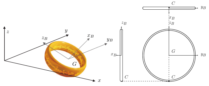
We want to analyze the motion of the ring with respect to an inertial reference frame $S_0 : \{O; B_0\}$ (with unit vectors $\boldsymbol{i}$, $\boldsymbol{j}$ and $\boldsymbol{k}$) as shown in the figure. We are going to consider the ring as a rigid body, with a body-fixed reference frame $S_B : \{G; B_B\}$ (with unit vectors $\boldsymbol{i}_B$, $\boldsymbol{j}_B$ and $\boldsymbol{k}_B$) attached to it. In the instant considered,

  • the ring is rolling without slipping.
  • the centre of mass $G$ and the axes $Gx_B$ and $Gz_B$ are contained in the plane $Oxz$
  • the angle between the axis $Ox$ and $Gx_B$ is $45^\circ$
  • the contact point of the ring with the plane $Oxy$ is $C$. The coordinates of $C$ in the body-fixed reference frame are $R(-1, 0, -19)/20$.
  • the velocity of $G$ is $\boldsymbol{v}_G = \Omega R \left(-\boldsymbol{i} + \frac{\sqrt{5}}{2}\boldsymbol{j} - \frac{9}{10}\boldsymbol{k}\right)$
  • the angular velocity fulfills the condition $\boldsymbol{\omega} \cdot \boldsymbol{i}_B = \boldsymbol{\omega} \cdot \boldsymbol{k}_B$

The mass of the ring is $M$ and the inertia tensor with respect to the reference frame $S_B$ is approximately given by

$$ \overline{\overline{I}}_G = MR^2 \begin{bmatrix} B & 0 & 0 \\ 0 & D & 0 \\ 0 & 0 & D \end{bmatrix} $$

where $B$, and $D$ are considered as constants.

...One Ring to rule them all

Ring with the inertial frame $S_0$ (axes $x$, $y$, $z$) and the body frame $S_B$ (axes $x_B$, $y_B$, $z_B$, centre $G$), with the contact point $C$, shown in an oblique view and in side and top views.
Figure: Ring with the inertial frame $S_0$ (axes $x$, $y$, $z$) and the body frame $S_B$ (axes $x_B$, $y_B$, $z_B$, centre $G$), with the contact point $C$, shown in an oblique view and in side and top views. (Problems.pdf, p. 41).
Worked Solution [ Click to Expand ]

Reference Frames, Bases and Degrees of Freedom

  • Physical system: the ring, one rigid body of mass $M$ and radius $R$, rolling without slipping on the plane $Oxy$; parts (a) and (b) are a snapshot, part (c) adds the attraction of Mordor, part (d) the values of the inertia constants.
  • Fixed frame: $S_0\{O; \mathcal B_0\}$, basis $\{\mathbf i, \mathbf j, \mathbf k\}$, with $\mathbf k$ normal to the ground plane $Oxy$ and pointing up (read from the figure).
  • Body frame: $S_B\{G; \mathcal B_B\}$ at the centre of the ring, basis $\{\mathbf i_B, \mathbf j_B, \mathbf k_B\}$. Read from the side views of the figure: the ring lies in the plane $Gy_Bz_B$, and $\mathbf i_B$ is the axis of the ring (normal to its plane). At this instant $Gx_B$ and $Gz_B$ are in the plane $Oxz$, $\mathbf i_B$ leans up and towards positive $x$, $\mathbf k_B$ up and towards negative $x$, and $\mathbf j_B$ is parallel to $\mathbf j$.
  • Degrees of freedom: a free rigid body has six. Keeping a point of the ring on the plane removes one; rolling without slipping adds the two conditions of zero tangential velocity at the contact point, which restrict velocities only (they are not integrable). At an instant, the condition of rolling makes the velocity of the body point $C$ in contact zero.
  • Basis of work: $\mathcal B_B$, where the inertia tensor and the coordinates of $C$ are given; the results are also written in $\mathcal B_0$ where it helps.
DatumValueSI unit
Mass, radius of the ring$M$, $R$kg, m
Angle from $Ox$ to $Gx_B$$45^\circ$, with $Gx_B$, $Gz_B$ and $G$ in the plane $Oxz$rad
Contact point $C$ in $S_B$$\mathbf r_G^C = \tfrac{R}{20}(-1, 0, -19)_B$, on the plane $Oxy$m
Velocity of $G$$\mathbf v_0^G = \Omega R\,(-\mathbf i + \tfrac{\sqrt5}{2}\,\mathbf j - \tfrac{9}{10}\,\mathbf k)$m/s
Condition on the angular velocity$\boldsymbol\omega_{B0}\cdot\mathbf i_B = \boldsymbol\omega_{B0}\cdot\mathbf k_B$rad/s
Inertia tensor about $G$$MR^2\,\mathrm{diag}(B, D, D)$ in $\mathcal B_B$kg m$^2$
Attraction of Mordorforce on each mass element proportional to $dm$ and to its distance from $O$, constant $\beta$N/(kg m)
  • Unknowns: the three components of $\boldsymbol\omega_{B0}$ and the instantaneous axis (a); $T_0$ and $\mathbf H_{G,0}$ (b); the force and moment about $G$ of the attraction (c); the constants $B$ and $D$ (d).
  • Count of equations: the zero velocity of $C$ gives three scalar equations, one of which contains no angular velocity (a check of the data); the condition of the statement closes the system.

Change of Basis, Position Vectors and Constraint Kinematics

The body basis: one rotation about j

i k iB kB cos 45° sin 45° −sin 45° cos 45° 45° 45° j = jB (⊗) rotation +45° about −j (out of the paper)
Figure 1. The body basis of the ring is $\mathcal B_0$ turned by $45^\circ$ about $-\mathbf j$ (out of the paper, $\mathbf j$ ⊗). The axis $\mathbf k_B$ leans to negative $\mathbf i$, which gives the minus sign of $[{}_0R_B]$.
Body basis: rotation about j by 45 degrees Law: simple rotation about the second axis, positive by the right-hand rule about the axis that points out of the paper Source: Notes.pdf, Eq. 1.19; Notes.pdf, Eq. 1.15; [Lecture 7, Slide 12]

View of the plane $Oxz$ with $\mathbf i$ to the right and $\mathbf k$ up. The vector out of the paper is then right times up, $\mathbf i\times\mathbf k = -\mathbf j$, so $\mathbf j$ points into the paper (⊗). The figure turns $Gx_B$ counterclockwise by 45 degrees from $Ox$: a positive rotation about the axis out of the paper, $-\mathbf j$.

$$\begin{aligned} \mathbf i_B &= \cos 45^\circ\,\mathbf i + \sin 45^\circ\,\mathbf k \quad &\text{(right triangle with hypotenuse 1: adjacent leg along $\mathbf i$, opposite leg along $\mathbf k$)} \\ \mathbf k_B &= -\sin 45^\circ\,\mathbf i + \cos 45^\circ\,\mathbf k \quad &\text{($\mathbf k$ turned counterclockwise about the axis out of the paper leans to negative $\mathbf i$)} \\ \mathbf j_B &= \mathbf j \quad &\text{(the rotation axis does not move)} \\ [{}_0R_B] &= \frac{1}{\sqrt2}\begin{bmatrix} 1 & 0 & -1 \cr 0 & \sqrt2 & 0 \cr 1 & 0 & 1 \end{bmatrix} \quad &\text{(columns: $\mathbf i_B$, $\mathbf j_B$, $\mathbf k_B$ in $\mathcal B_0$)} \\ \det[{}_0R_B] &= 1\cdot\left(\tfrac{1}{\sqrt2}\cdot\tfrac{1}{\sqrt2} - \left(-\tfrac{1}{\sqrt2}\right)\tfrac{1}{\sqrt2}\right) = 1 \quad &\text{(expand along the second row)} \\ [{}_0R_B][{}_0R_B]^T &= \frac12\begin{bmatrix} 1 + 1 & 0 & 1 - 1 \cr 0 & 2 & 0 \cr 1 - 1 & 0 & 1 + 1 \end{bmatrix} = [U] \quad &\text{(row by row products)} \\ \mathbf j_B\times\mathbf k_B &= \mathbf j\times\frac{-\mathbf i + \mathbf k}{\sqrt2} = \frac{\mathbf k + \mathbf i}{\sqrt2} = \mathbf i_B \quad &\text{(right-handed check: $\mathbf j\times\mathbf i = -\mathbf k$, $\mathbf j\times\mathbf k = \mathbf i$)} \end{aligned}$$
$$\boxed{\mathbf i_B = \frac{\mathbf i + \mathbf k}{\sqrt2}, \qquad \mathbf j_B = \mathbf j, \qquad \mathbf k_B = \frac{-\mathbf i + \mathbf k}{\sqrt2}}$$

Units: dimensionless

Meaning: the ring is tilted by 45 degrees: its axis $\mathbf i_B$ and its diameter $\mathbf k_B$ make 45 degrees with the ground; the diameter $\mathbf j_B$ stays horizontal.

Position of the contact point and height of G

ground plane Oxy (z = 0) rGC R/20 19R/20 zG = √2 R/2 9√2 R/20 iB kB G C j = jB
Figure 2. Section of the ring by the plane $Oxz$. The coordinates of $C$ in the body frame, turned into $\mathcal B_0$, give the height of $G$, $\sqrt2 R/2$, and the horizontal offset $9\sqrt2 R/20$ of the contact point.
Contact point in the fixed basis and position of G Law: components of a vector in another basis; the contact point lies on the plane z = 0 Source: Notes.pdf, Eq. 1.12; Problems.pdf, p. 41
$$\begin{aligned} [\mathbf r_G^C]_0 &= [{}_0R_B]\,[\mathbf r_G^C]_B = \frac{1}{\sqrt2}\begin{bmatrix} 1 & 0 & -1 \cr 0 & \sqrt2 & 0 \cr 1 & 0 & 1 \end{bmatrix}\frac{R}{20}\begin{bmatrix} -1 \cr 0 \cr -19 \end{bmatrix} \quad &\text{(change of basis of the datum)} \\ &= \frac{R}{20\sqrt2}\begin{bmatrix} -1 + 19 \cr 0 \cr -1 - 19 \end{bmatrix} = \frac{R}{20\sqrt2}\begin{bmatrix} 18 \cr 0 \cr -20 \end{bmatrix} \quad &\text{(row by column products)} \\ &= \begin{bmatrix} \tfrac{9\sqrt2}{20}R \cr 0 \cr -\tfrac{\sqrt2}{2}R \end{bmatrix} \quad &\text{(simplify)} \\ z_C &= z_G - \frac{\sqrt2}{2}R = 0 \quad &\text{(C on the ground plane)} \\ z_G &= \frac{\sqrt2}{2}R, \qquad y_G = 0 \quad &\text{(solve; $G$ is in the plane $Oxz$)} \end{aligned}$$
$$\boxed{\mathbf r_G^C = \frac{9\sqrt2}{20}R\,\mathbf i - \frac{\sqrt2}{2}R\,\mathbf k, \qquad \mathbf r_0^G = x_G\,\mathbf i + \frac{\sqrt2}{2}R\,\mathbf k}$$

Units: $[\mathrm L]$

Meaning: the centre of the tilted ring is at the height $R/\sqrt2$, and the contact point lies slightly to the side of the ring (the component $-R/20$ along the axis $\mathbf i_B$ is the half width of the band). The abscissa $x_G$ is not given by the statement and stays as a symbol.

Rolling condition and angular velocity

Velocity of G in the body basis Law: components of a vector in another basis, with the inverse matrix equal to the transpose Source: Notes.pdf, Eq. 1.12; Notes.pdf, Eq. 1.14
$$\begin{aligned} [\mathbf v_0^G]_B &= [{}_0R_B]^T[\mathbf v_0^G]_0 = \frac{1}{\sqrt2}\begin{bmatrix} 1 & 0 & 1 \cr 0 & \sqrt2 & 0 \cr -1 & 0 & 1 \end{bmatrix}\Omega R\begin{bmatrix} -1 \cr \tfrac{\sqrt5}{2} \cr -\tfrac{9}{10} \end{bmatrix} \quad &\text{(transpose of the matrix; data)} \\ &= \frac{\Omega R}{\sqrt2}\begin{bmatrix} -1 - \tfrac{9}{10} \cr \tfrac{\sqrt{10}}{2} \cr 1 - \tfrac{9}{10} \end{bmatrix} \quad &\text{(row by column products)} \\ &= \Omega R\begin{bmatrix} -\tfrac{19\sqrt2}{20} \cr \tfrac{\sqrt5}{2} \cr \tfrac{\sqrt2}{20} \end{bmatrix} \quad &\text{(rationalize: one over root two is root two over two)} \end{aligned}$$
$$\boxed{\mathbf v_0^G = \Omega R\left(-\frac{19\sqrt2}{20}\,\mathbf i_B + \frac{\sqrt5}{2}\,\mathbf j_B + \frac{\sqrt2}{20}\,\mathbf k_B\right)}$$

Units: $[\mathrm{L\,T^{-1}}]$

Meaning: the centre moves against the axis of the ring and along the horizontal diameter $\mathbf j_B$, with a small component along $\mathbf k_B$.

Consistency of the data with rolling Law: equal projections of the velocities of two body points on the segment that joins them; zero velocity of the contact point Source: Notes.pdf, Eq. 9.7; Notes.pdf, Eq. 9.3
$$\begin{aligned} \mathbf v_0^C\cdot\mathbf r_G^C &= \mathbf v_0^G\cdot\mathbf r_G^C \quad &\text{(Eq. 9.7)} \\ 0 &= \mathbf v_0^G\cdot\mathbf r_G^C \quad &\text{(rolling without slipping: the body point in contact is at rest)} \\ \mathbf v_0^G\cdot\mathbf r_G^C &= \frac{\Omega R^2}{20}\left[\left(-\tfrac{19\sqrt2}{20}\right)(-1) + \tfrac{\sqrt5}{2}\cdot 0 + \tfrac{\sqrt2}{20}\,(-19)\right] \quad &\text{(components in $\mathcal B_B$)} \\ &= \frac{\Omega R^2}{20}\left(\tfrac{19\sqrt2}{20} - \tfrac{19\sqrt2}{20}\right) = 0 \quad &\text{(the two terms cancel)} \end{aligned}$$
$$\boxed{\mathbf v_0^G\cdot\mathbf r_G^C = 0 \ \text{(the data are compatible with rolling)}}$$

Units: $[\mathrm{L^2\,T^{-1}}]$

Meaning: the velocity of the centre is perpendicular to the segment from the centre to the contact point, as it must be when the contact point is at rest.

Angular velocity from the rolling condition Law: velocity field from $G$ to the contact point $C$, with zero velocity at $C$; vector product by its determinant Source: Notes.pdf, Eq. 9.3; Notes.pdf, Eq. 1.31; [Lecture 7, Slide 6]

The condition of the statement lets the angular velocity be written as $\boldsymbol\omega_{B0} = p\,\mathbf i_B + q\,\mathbf j_B + p\,\mathbf k_B$.

$$\begin{aligned} \mathbf 0 &= \mathbf v_0^G + \boldsymbol\omega_{B0}\times\mathbf r_G^C \quad &\text{(velocity field from $G$ to $C$; rolling)} \\ \boldsymbol\omega_{B0}\times\mathbf r_G^C &= \frac{R}{20}\begin{vmatrix} \mathbf i_B & \mathbf j_B & \mathbf k_B \cr p & q & p \cr -1 & 0 & -19 \end{vmatrix} \quad &\text{(determinant form)} \\ &= \frac{R}{20}\left[\mathbf i_B\,(-19q - 0) - \mathbf j_B\,(-19p + p) + \mathbf k_B\,(0 + q)\right] \quad &\text{(expand along the first row)} \\ &= \frac{R}{20}\left(-19q\,\mathbf i_B + 18p\,\mathbf j_B + q\,\mathbf k_B\right) \quad &\text{(carry out the products)} \\ -\frac{19\sqrt2}{20}\,\Omega R - \frac{19}{20}\,qR &= 0 \quad &\text{($\mathbf i_B$ component)} \\ q &= -\sqrt2\,\Omega \quad &\text{(solve)} \\ \frac{\sqrt5}{2}\,\Omega R + \frac{18}{20}\,pR &= 0 \quad &\text{($\mathbf j_B$ component)} \\ p &= -\frac{10\sqrt5}{18}\,\Omega = -\frac{5\sqrt5}{9}\,\Omega \quad &\text{(solve)} \\ \frac{\sqrt2}{20}\,\Omega R + \frac{1}{20}\,qR &= 0 \quad &\text{($\mathbf k_B$ component: satisfied by the same $q$, the check of the previous box)} \\ \omega_{B0}^2 &= 2\cdot\frac{125}{81}\,\Omega^2 + 2\,\Omega^2 = \frac{412}{81}\,\Omega^2 \quad &\text{(squared modulus)} \end{aligned}$$
$$\boxed{\boldsymbol\omega_{B0} = -\Omega\left(\frac{5\sqrt5}{9}\,\mathbf i_B + \sqrt2\,\mathbf j_B + \frac{5\sqrt5}{9}\,\mathbf k_B\right), \qquad \omega_{B0} = \frac{2\sqrt{103}}{9}\,\Omega \approx 2.255\,\Omega}$$

Units: $[\mathrm{L\,T^{-1}}] = [\mathrm{T^{-1}}][\mathrm L]$, so $p$ and $q$ are in $[\mathrm{T^{-1}}]$

Meaning: the component along the axis $\mathbf i_B$ is the spin of the ring as it rolls; the components along the diameters $\mathbf j_B$ and $\mathbf k_B$ describe how its plane turns and tilts.

Angular velocity in the fixed basis Law: components of a vector in another basis Source: Notes.pdf, Eq. 1.12
$$\begin{aligned} [\boldsymbol\omega_{B0}]_0 &= [{}_0R_B][\boldsymbol\omega_{B0}]_B = \frac{1}{\sqrt2}\begin{bmatrix} 1 & 0 & -1 \cr 0 & \sqrt2 & 0 \cr 1 & 0 & 1 \end{bmatrix}\begin{bmatrix} p \cr q \cr p \end{bmatrix} \quad &\text{(change of basis)} \\ &= \begin{bmatrix} (p - p)/\sqrt2 \cr q \cr (p + p)/\sqrt2 \end{bmatrix} = \begin{bmatrix} 0 \cr q \cr \sqrt2\,p \end{bmatrix} \quad &\text{(row by column products)} \end{aligned}$$
$$\boxed{\boldsymbol\omega_{B0} = -\Omega\left(\sqrt2\,\mathbf j + \frac{5\sqrt{10}}{9}\,\mathbf k\right)}$$

Units: $[\mathrm{T^{-1}}]$

Meaning: the equal components along $\mathbf i_B$ and $\mathbf k_B$ cancel along $\mathbf i$: the angular velocity has no component along $Ox$ and lies in the vertical plane through $\mathbf j$ and $\mathbf k$.

Instantaneous axis of rotation

Instantaneous axis of rotation Law: a body point of zero velocity lies on the instantaneous axis; the slip velocity is zero when one body point is at rest Source: Notes.pdf, Eq. 9.5; Notes.pdf, Eq. 9.8; Notes.pdf, Eq. 9.11; [Lecture 7, Slide 9]
$$\begin{aligned} \mathbf v_0^C &= \mathbf 0 \quad &\text{(rolling without slipping)} \\ v_{0\parallel} &= \mathbf v_0^C\cdot\mathbf e_\omega = 0 \quad &\text{(slip speed, the same for all body points, Eq. 9.5)} \\ \mathbf v_0^G\cdot\boldsymbol\omega_{B0} &= \Omega R\cdot\Omega\left[\tfrac{19\sqrt2}{20}\cdot\tfrac{5\sqrt5}{9} - \tfrac{\sqrt5}{2}\sqrt2 - \tfrac{\sqrt2}{20}\cdot\tfrac{5\sqrt5}{9}\right] \quad &\text{(check with $G$, components in $\mathcal B_B$)} \\ &= \Omega^2R\sqrt{10}\left[\tfrac{95 - 5}{180} - \tfrac12\right] = 0 \quad &\text{(common factor $\sqrt{10}$; $90/180$ is one half)} \\ \mathbf r_0^C &= \mathbf r_0^G + \mathbf r_G^C = \left(x_G + \tfrac{9\sqrt2}{20}R\right)\mathbf i \quad &\text{(position of $C$ from the box of the contact point)} \end{aligned}$$
$$\boxed{\text{axis: } \mathbf r_0^P = \left(x_G + \tfrac{9\sqrt2}{20}R\right)\mathbf i + \lambda\left(\sqrt2\,\mathbf j + \tfrac{5\sqrt{10}}{9}\,\mathbf k\right)}$$

Units: $[\mathrm L]$; the parameter $\lambda$ is a length

Meaning: the ring turns, at this instant, about the line through the contact point parallel to the angular velocity. The motion is a pure rotation: every body point moves perpendicular to that line.

Center of Mass and Inertia Tensor

The centre of mass is the centre $G$ of the ring (the planes $Gx_By_B$, $Gx_Bz_B$ and $Gy_Bz_B$ are planes of symmetry of the band). The statement gives the inertia tensor about $G$ in $\mathcal B_B$ with two constants; part (d) fixes them. The relation used is the sum of the three moments of inertia; a thin circular wire is then used as an independent check.

Part (d): the constants B and D Law: the polar moment of inertia about a point is half the sum of the moments about three orthogonal axes through it Source: Notes.pdf, Eq. 10.13; Notes.pdf, Eq. 10.38; [Lecture 8, Slide 10]
$$\begin{aligned} 2\,I_G &= I_{x_B} + I_{y_B} + I_{z_B} \quad &\text{(Eq. 10.13 at the point $G$)} \\ 2\,MR^2 &= MR^2\,(B + D + D) \quad &\text{(datum and diagonal of the tensor)} \\ B + 2D &= 2 \quad &\text{(divide by $MR^2$)} \\ 2D + 2D &= 2 \quad &\text{(datum: $B$ is twice $D$)} \\ D &= \frac12, \qquad B = 1 \quad &\text{(solve)} \end{aligned}$$
$$\boxed{B = 1, \qquad D = \frac12, \qquad \bar{\bar I}_G = MR^2\,\mathrm{diag}\left(1, \tfrac12, \tfrac12\right)_{BB}}$$

Units: $B$ and $D$ are pure numbers; the tensor is in kg m$^2$

Meaning: the moment about the axis of the ring is twice the moment about a diameter, as for any flat body (the moment about the normal axis is the sum of the two in-plane ones).

Check: moments of inertia of a thin circular ring by integration Law: definition of the moment of inertia about an axis; mass element of a homogeneous wire Source: Notes.pdf, Eq. 10.11; Notes.pdf, Sec. 10.5; [Lecture 8, Slide 10]

Model the ring as a wire of radius $R$ in the plane $Gy_Bz_B$, with the point at angle $\phi$ at $y_B = R\cos\phi$ and $z_B = R\sin\phi$.

$$\begin{aligned} dm &= \frac{M}{2\pi R}\,R\,d\phi = \frac{M}{2\pi}\,d\phi \quad &\text{(linear density times the arc length $R\,d\phi$)} \\ I_{x_B} &= \int_0^{2\pi}\left(y_B^2 + z_B^2\right)dm = \int_0^{2\pi} R^2\,\frac{M}{2\pi}\,d\phi \quad &\text{(distance to the axis $\mathbf i_B$ is $R$; $x_B = 0$)} \\ &= \frac{MR^2}{2\pi}\,\big[\phi\big]_0^{2\pi} = \frac{MR^2}{2\pi}\,(2\pi - 0) = MR^2 \quad &\text{(Barrow with both limits)} \\ I_{y_B} &= \int_0^{2\pi}\left(x_B^2 + z_B^2\right)dm = \frac{MR^2}{2\pi}\int_0^{2\pi}\sin^2\phi\,d\phi \quad &\text{(distance to the axis $\mathbf j_B$: $z_B$ only)} \\ &= \frac{MR^2}{2\pi}\int_0^{2\pi}\frac{1 - \cos 2\phi}{2}\,d\phi \quad &\text{(double-angle identity)} \\ &= \frac{MR^2}{2\pi}\left[\frac{\phi}{2} - \frac{\sin 2\phi}{4}\right]_0^{2\pi} = \frac{MR^2}{2\pi}\left(\pi - 0 - 0 + 0\right) = \frac{MR^2}{2} \quad &\text{(antiderivative; Barrow with both limits)} \\ I_{z_B} &= I_{y_B} = \frac{MR^2}{2} \quad &\text{(same steps with $\cos^2\phi$, whose integral over a period is also $\pi$)} \end{aligned}$$
$$\boxed{I_{x_B} = MR^2, \qquad I_{y_B} = I_{z_B} = \frac{MR^2}{2}}$$

Units: $[\mathrm M][\mathrm L^2]$

Meaning: the thin-wire model gives exactly the values of part (d), and its polar moment, half of the sum, is $MR^2$, the datum of the statement. The products of inertia vanish because the three coordinate planes are planes of symmetry.

Linear Momentum, Angular Momentum and Kinetic Energy

Linear momentum and angular momentum about G Law: linear momentum from the velocity of $G$; angular momentum about $G$ from the inertia tensor Source: Notes.pdf, Eq. 11.3; Notes.pdf, Eq. 11.12; Notes.pdf, Eq. 11.19; [Lecture 9, Slide 5]
$$\begin{aligned} \mathbf p_0 &= M\,\mathbf v_0^G \quad &\text{(Eq. 11.3)} \\ \mathbf H_{G,0} &= \bar{\bar I}_G\cdot\boldsymbol\omega_{B0} \quad &\text{(Eq. 11.12 with $A$ at $G$; equal in $S_0$ and $S_G$, Eq. 11.19)} \\ [\mathbf H_{G,0}]_B &= MR^2\begin{bmatrix} B & 0 & 0 \cr 0 & D & 0 \cr 0 & 0 & D \end{bmatrix}\begin{bmatrix} p \cr q \cr p \end{bmatrix} = MR^2\begin{bmatrix} Bp \cr Dq \cr Dp \end{bmatrix} \quad &\text{(row by column products)} \\ &= -MR^2\Omega\begin{bmatrix} \tfrac{5\sqrt5}{9}B \cr \sqrt2\,D \cr \tfrac{5\sqrt5}{9}D \end{bmatrix} \quad &\text{(values of $p$ and $q$)} \end{aligned}$$
$$\boxed{\mathbf H_{G,0} = -M\Omega R^2\left(\frac{5\sqrt5}{9}\,B\,\mathbf i_B + \sqrt2\,D\,\mathbf j_B + \frac{5\sqrt5}{9}\,D\,\mathbf k_B\right)}$$

Units: $[\mathrm M][\mathrm L^2][\mathrm{T^{-1}}]$

Meaning: with $B$ different from $D$ the angular momentum is not parallel to the angular velocity: the spin about the axis of the ring is weighted by the larger moment $B$.

Kinetic energy by Koenig's decomposition Law: kinetic energy of a rigid body: translation of $G$ plus rotation about $G$ Source: Notes.pdf, Eq. 11.31; Notes.pdf, Eq. 11.37; [Lecture 9, Slide 10]
$$\begin{aligned} T_0 &= \frac12\,M\left(v_0^G\right)^2 + \frac12\,\boldsymbol\omega_{B0}\cdot\bar{\bar I}_G\cdot\boldsymbol\omega_{B0} \quad &\text{(Eq. 11.31)} \\ \left(v_0^G\right)^2 &= \Omega^2R^2\left(1 + \tfrac54 + \tfrac{81}{100}\right) = \frac{306}{100}\,\Omega^2R^2 = \frac{153}{50}\,\Omega^2R^2 \quad &\text{(sum of the squared components in $\mathcal B_0$)} \\ \boldsymbol\omega_{B0}\cdot\bar{\bar I}_G\cdot\boldsymbol\omega_{B0} &= MR^2\left(Bp^2 + Dq^2 + Dp^2\right) \quad &\text{(scalar product of $\boldsymbol\omega_{B0}$ with the previous box)} \\ &= MR^2\Omega^2\left(\frac{125}{81}B + 2D + \frac{125}{81}D\right) = \frac{MR^2\Omega^2}{81}\left(125B + 287D\right) \quad &\text{(squares of $p$ and $q$; common denominator 81)} \\ T_0 &= \frac{153}{100}\,M\Omega^2R^2 + \frac{125B + 287D}{162}\,M\Omega^2R^2 \quad &\text{(add both halves)} \end{aligned}$$
$$\boxed{T_0 = M\Omega^2R^2\left(\frac{153}{100} + \frac{125B + 287D}{162}\right) = \frac{M\Omega^2R^2}{8100}\left(12393 + 6250B + 14350D\right)}$$

Units: $[\mathrm M][\mathrm L^2][\mathrm{T^{-2}}]$ (J)

Meaning: with the values of part (d), one and one half, the energy is $\tfrac{4303}{1350}\,M\Omega^2R^2 \approx 3.187\,M\Omega^2R^2$: a little less than half of it is translation of the centre and the rest is rotation.

Free-Body Diagram and Equations of Motion

Only the attraction of Mordor is asked for (part (c)); the weight and the contact force at $C$ are not part of the question, and no equation of motion is requested.

i j k dF = −β r0P dm r0P rGP P F = −β M r0G G MG = 0 Mordor (O)
Figure 3. The attraction of Mordor on each element points to $O$ and is proportional to $dm$ and to the distance. Its resultant is $-\beta M\,\mathbf r_0^G$, applied at $G$, with zero moment about $G$.
Part (c): resultant force of the attraction of Mordor Law: an attraction towards $O$ proportional to the mass element and to its distance; definition of the centre of mass Source: Notes.pdf, Eq. 10.7; Notes.pdf, Eq. 12.14; [Lecture 10, Slide 9]
$$\begin{aligned} d\mathbf F &= -\beta\,\mathbf r_0^P\,dm \quad &\text{(modulus $\beta\,r_0^P\,dm$, directed from $P$ towards $O$: hence the minus sign)} \\ \mathbf F_{\mathcal M} &= \int_{\mathcal R} -\beta\,\mathbf r_0^P\,dm = -\beta\int_{\mathcal R}\mathbf r_0^P\,dm \quad &\text{(sum over the ring; $\beta$ is constant)} \\ &= -\beta M\,\mathbf r_0^G \quad &\text{(first moment of the mass, Eq. 10.7)} \\ &= -\beta M\left(x_G\,\mathbf i + \frac{\sqrt2}{2}R\,\mathbf k\right) \quad &\text{(position of $G$ found above)} \end{aligned}$$
$$\boxed{\mathbf F_{\mathcal M} = -\beta M\,\mathbf r_0^G = -\beta M\left(x_G\,\mathbf i + \frac{\sqrt2}{2}R\,\mathbf k\right)}$$

Units: $\beta$ in $[\mathrm{T^{-2}}]$ (N per kg per m), so $[\mathrm{T^{-2}}][\mathrm M][\mathrm L] = [\mathrm{M\,L\,T^{-2}}]$

Meaning: the distributed attraction acts like a single spring of stiffness $\beta M$ between $O$ and the centre of mass.

Part (c): moment of the attraction about G Law: moment of a distributed force about a point; the first moment about the centre of mass vanishes Source: Notes.pdf, Eq. 12.14; Notes.pdf, Eq. 10.44; [Lecture 10, Slide 12]
$$\begin{aligned} \mathbf M_{G,\mathcal M} &= \int_{\mathcal R}\mathbf r_G^P\times d\mathbf F = -\beta\int_{\mathcal R}\mathbf r_G^P\times\mathbf r_0^P\,dm \quad &\text{(Eq. 12.14 summed over the mass elements)} \\ &= -\beta\int_{\mathcal R}\mathbf r_G^P\times\left(\mathbf r_0^G + \mathbf r_G^P\right)dm \quad &\text{(position of $P$ through $G$)} \\ &= -\beta\left(\int_{\mathcal R}\mathbf r_G^P\,dm\right)\times\mathbf r_0^G - \beta\int_{\mathcal R}\mathbf r_G^P\times\mathbf r_G^P\,dm \quad &\text{(distribute; $\mathbf r_0^G$ is the same for all elements)} \\ &= -\beta\,\mathbf 0\times\mathbf r_0^G - \mathbf 0 \quad &\text{(Eq. 10.44; a vector crossed with itself is zero)} \end{aligned}$$
$$\boxed{\mathbf M_{G,\mathcal M} = \mathbf 0}$$

Units: $[\mathrm{M\,L^2\,T^{-2}}]$ (N m)

Meaning: like uniform gravity, this attraction is equivalent to a single force applied at $G$; it cannot change the angular momentum about the centre of mass.

Answers and Checks

AskedAnswer
(a) Instantaneous axis of rotationthrough the contact point $C$, at $(x_G + \tfrac{9\sqrt2}{20}R)\,\mathbf i$, parallel to $\boldsymbol\omega_{B0} = -\Omega(\tfrac{5\sqrt5}{9}\mathbf i_B + \sqrt2\,\mathbf j_B + \tfrac{5\sqrt5}{9}\mathbf k_B) = -\Omega(\sqrt2\,\mathbf j + \tfrac{5\sqrt{10}}{9}\mathbf k)$; zero slip
(b) Kinetic energy$T_0 = M\Omega^2R^2[\tfrac{153}{100} + \tfrac{125B + 287D}{162}]$; with part (d), $\tfrac{4303}{1350}M\Omega^2R^2$
(b) Angular momentum about $G$$\mathbf H_{G,0} = -M\Omega R^2(\tfrac{5\sqrt5}{9}B\,\mathbf i_B + \sqrt2\,D\,\mathbf j_B + \tfrac{5\sqrt5}{9}D\,\mathbf k_B)$
(c) Force and moment of Mordor$\mathbf F_{\mathcal M} = -\beta M\,\mathbf r_0^G$, $\mathbf M_{G,\mathcal M} = \mathbf 0$
(d) Inertia constants$B = 1$, $D = 1/2$

Check against the official key: the key (Problems.pdf, p. 78) prints only part (c): the force is $\beta M\,\mathbf r_0^G$ and the moment about $G$ is zero. The moment matches. The force matches in modulus and line of action; its sign differs.

Discrepancy with the official solution

The key writes the force as the integral of $\beta\,\mathbf r_0^P\,dm$, which points away from $O$ for a positive constant. The statement says that Mordor attracts the ring, so each element is pulled towards $O$ and this solution writes the integral of $-\beta\,\mathbf r_0^P\,dm$, which gives $-\beta M\,\mathbf r_0^G$. The two expressions coincide if the constant of the key is read as a signed constant, negative for an attraction. The moment about $G$ is zero with either sign, because the first moment of the mass about $G$ vanishes. The key prints no answer for parts (a), (b) and (d).

Limiting cases and consistency:

  • Rolling check. The velocity of $G$ found from the angular velocity and the contact point, through the velocity field, reproduces the datum in all three components (the $\mathbf k_B$ component was not used to find $q$ and agrees with it).
  • Speed against distance to the axis. In a pure rotation the speed of $G$ equals the angular speed times the distance from $G$ to the axis. The speed of $G$ is about $1.749\,\Omega R$. The segment from $G$ to $C$ has length about $0.951\,R$ and makes with the angular velocity an angle of cosine about $0.579$, so the distance from $G$ to the axis is about $0.776\,R$; times the angular speed, about $2.255\,\Omega$, it gives $1.749\,\Omega R$ again.
  • Thin ring. The values of part (d) are those of a thin circular wire, computed by integration in the inertia section.

Interactive geometry simulator: it needs JavaScript. The figures above show the same geometry.

Planar and 3D rigid body dynamics, equilibrium and linearized oscillations

Problem RB 08

Triangle with spring and vertical constraint

Original statement · Problems.pdf, p. 42
Group D: DynamicsIn-Class Session 19

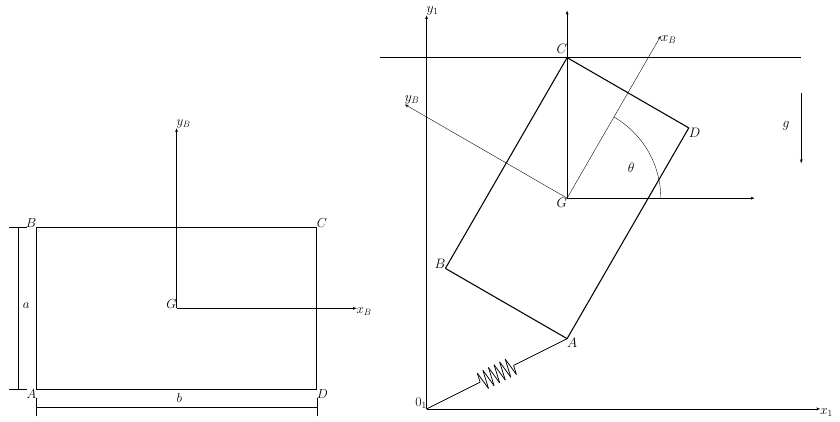
The planar equilateral triangle has side length $a$ and uniform mass $m$. It moves in the vertical plane $Oxy$ of the inertial frame $S_0 : \{O, B_0\}$ with $B_0 : \{\boldsymbol{i}, \boldsymbol{j}, \boldsymbol{k}\}$. The vertex $A$ of the triangle is connect [sic] to $O$ by a spring with constant $k$ and zero nominal length. The center of mass $G$ of the triangle is constrained to move along the vertical line $x = 2a$ without friction.

Equilateral triangle with vertices $A$, $B$, $C$ and centre $G$ in its body frame and with the frame $x_1y_1$ (left), and the triangle in the vertical plane with the spring $k$ from $O$, the vertical line $x = 2a$, the angle $\theta$ and the gravity $g$ (right).
Figure: Equilateral triangle with vertices $A$, $B$, $C$ and centre $G$ in its body frame and with the frame $x_1y_1$ (left), and the triangle in the vertical plane with the spring $k$ from $O$, the vertical line $x = 2a$, the angle $\theta$ and the gravity $g$ (right). (Problems.pdf, p. 42).
Worked Solution [ Click to Expand ]

Reference Frames, Bases and Degrees of Freedom

  • Physical system: a homogeneous equilateral triangular plate $ABC$ of side $a$ and mass $m$, moving in the vertical plane $Oxy$. The vertex $A$ is tied to $O$ by a spring of stiffness $k$ and zero natural length; the centre of mass $G$ slides without friction along the vertical line through the point at abscissa $2a$. Gravity acts along $-\mathbf j$ (read from the figure).
  • Fixed frame: $S_0\{O; \mathcal B_0\}$, $\mathbf i$ horizontal to the right, $\mathbf j$ vertical upwards, $\mathbf k$ out of the paper (⊙). It is inertial.
  • Body frames: $S_B\{G; \mathbf i_B, \mathbf j_B, \mathbf k\}$, with $\mathbf j_B$ along the axis of symmetry from $G$ towards $A$ and $\mathbf i_B$ parallel to $BC$, from $B$ towards $C$; and the frame $x_1y_1$ of the left figure, parallel to it, with origin at the midpoint $M$ of $BC$ (read from the figure: $Mx_1$ along $BC$, $My_1$ through $A$).
  • Coordinates: the height $y_G$ of $G$ and the angle $\theta$ from $\mathbf i$ to $\mathbf i_B$, positive counterclockwise about $\mathbf k$ (the figure draws it between $OX$ and the line of $GX_B$).
  • Degrees of freedom: a rigid body in plane motion has three (two coordinates of $G$ and one angle); the guide fixes the abscissa of $G$, which leaves two, $y_G$ and $\theta$.
  • Unknowns of the dynamics: $y_G(t)$, $\theta(t)$ and the guide reaction $R$ (a force along $\mathbf i$, because a smooth guide cannot push along its own direction). Three scalar equations are needed: the two components of the force equation and the component along $\mathbf k$ of the moment equation.
DatumSymbolSI unit
Side of the triangle$a$m
Mass, homogeneous$m$kg
Spring stiffness, zero natural length, from $O$ to $A$$k$N/m
Gravity$g$, along $-\mathbf j$m/s$^2$
Guide of $G$vertical line at abscissa $2a$, smoothm
Initial velocity of $A$ (part d)$u_0\,\mathbf i + v_0\,\mathbf j$m/s
Equilibrium angle (part e)$\pi/4$rad

Change of Basis, Position Vectors and Constraint Kinematics

i j iB jB cos θ sin θ −sin θ cos θ θ θ k (⊙) at G
Figure 1. Body basis of the triangle, turned by $\theta$ about $\mathbf k$ (⊙). The axis $\mathbf j_B$ leans to negative $\mathbf i$, which gives the minus sign of $[{}_0R_B]$.
Body basis: rotation about k by the angle theta Law: simple rotation about the third axis, positive by the right-hand rule Source: Notes.pdf, Eq. 1.20; Notes.pdf, Eq. 1.15; [Lecture 7, Slide 12]

View of the plane of motion with $\mathbf k$ out of the paper (⊙), $\mathbf i$ to the right and $\mathbf j$ up; positive $\theta$ is counterclockwise.

$$\begin{aligned} \mathbf i_B &= \cos\theta\,\mathbf i + \sin\theta\,\mathbf j \quad &\text{(right triangle with hypotenuse 1: adjacent leg along $\mathbf i$, opposite leg along $\mathbf j$)} \\ \mathbf j_B &= -\sin\theta\,\mathbf i + \cos\theta\,\mathbf j \quad &\text{($\mathbf j$ turned counterclockwise about $\mathbf k$, out of the paper, leans to negative $\mathbf i$)} \\ [{}_0R_B] &= \begin{bmatrix} \cos\theta & -\sin\theta & 0 \cr \sin\theta & \cos\theta & 0 \cr 0 & 0 & 1 \end{bmatrix} \quad &\text{(columns: $\mathbf i_B$, $\mathbf j_B$, $\mathbf k$ in $\mathcal B_0$)} \\ \det[{}_0R_B] &= 1\cdot\left(\cos^2\theta + \sin^2\theta\right) = 1 \quad &\text{(expand along the third row)} \\ [{}_0R_B][{}_0R_B]^T &= \begin{bmatrix} \cos^2\theta + \sin^2\theta & \cos\theta\sin\theta - \sin\theta\cos\theta & 0 \cr \sin\theta\cos\theta - \cos\theta\sin\theta & \sin^2\theta + \cos^2\theta & 0 \cr 0 & 0 & 1 \end{bmatrix} = [U] \quad &\text{(row by row products)} \\ \boldsymbol\omega_{B0} &= \dot\theta\,\mathbf k, \qquad \boldsymbol\alpha_{B0} = \ddot\theta\,\mathbf k \quad &\text{(single rotation about the fixed axis $\mathbf k$; product rule with $\dot{\mathbf k} = \mathbf 0$)} \\ \dot{\mathbf i}_B &= \boldsymbol\omega_{B0}\times\mathbf i_B = \dot\theta\,\mathbf j_B, \qquad \dot{\mathbf j}_B = \boldsymbol\omega_{B0}\times\mathbf j_B = -\dot\theta\,\mathbf i_B \quad &\text{(Poisson: $\mathbf k\times\mathbf i_B = \mathbf j_B$, $\mathbf k\times\mathbf j_B = -\mathbf i_B$)} \end{aligned}$$
$$\boxed{\mathbf i_B = \cos\theta\,\mathbf i + \sin\theta\,\mathbf j, \qquad \mathbf j_B = -\sin\theta\,\mathbf i + \cos\theta\,\mathbf j, \qquad \boldsymbol\omega_{B0} = \dot\theta\,\mathbf k}$$

Units: the matrix is dimensionless; $\boldsymbol\omega_{B0}$ in $[\mathrm{T^{-1}}]$

Meaning: for $\theta$ equal to zero the side $BC$ is horizontal and $A$ is above it; for $\theta$ equal to $\pi/4$, as in the figure, $A$ is up and to the left of $G$.

Geometry of the triangle

x1 y1 iB jB A B C M G a/2 a √3 a/6 √3 a/3 = a/√3 h = √3 a/2
Figure 2. The right triangle $MCA$ gives the height $h = \sqrt3 a/2$; $G$ is at one third of it above $BC$, so $GA = a/\sqrt3$.
Height of the triangle and distance from G to A Law: Pythagoras in the right triangle formed by half the base, the height and one side Source: Problems.pdf, p. 42; Notes.pdf, Eq. 10.8

The triangle $MCA$ has its right angle at $M$: hypotenuse $AC$ of length $a$, leg $MC$ of length $a/2$, leg $MA$ equal to the height $h$.

$$\begin{aligned} h^2 + \left(\frac a2\right)^2 &= a^2 \quad &\text{(Pythagoras in the triangle $MCA$)} \\ h &= \sqrt{a^2 - \frac{a^2}{4}} = \frac{\sqrt3}{2}\,a \quad &\text{(positive root)} \\ \mathbf r_M^G &= \frac{\sqrt3}{6}\,a\,\mathbf j_B \quad &\text{(centre of mass at one third of the height: part (a), Center of mass section)} \\ \mathbf r_G^A &= \mathbf r_M^A - \mathbf r_M^G = \left(\frac{\sqrt3}{2} - \frac{\sqrt3}{6}\right)a\,\mathbf j_B = \frac{\sqrt3}{3}\,a\,\mathbf j_B \quad &\text{(A at the top of the height)} \end{aligned}$$
$$\boxed{h = \frac{\sqrt3}{2}\,a, \qquad \mathbf r_G^A = \frac{a}{\sqrt3}\,\mathbf j_B}$$

Units: $[\mathrm L]$

Meaning: the vertex $A$ is at two thirds of the height above the base, that is at the distance $a/\sqrt3$ from the centre of mass, along the axis of symmetry.

Position vectors

i j k (⊙) O x = 2a r0A rGA a/√3 (a/√3) cos θ (a/√3) sin θ θ G B C A
Figure 3. Position of $A$: the segment $GA$ of length $a/\sqrt3$ makes the angle $\theta$ with the vertical; its horizontal leg (opposite) points to negative $\mathbf i$ and its vertical leg (adjacent) to $\mathbf j$.
Positions of G and of A Law: constraint of the guide; position vector built as a sum of segments Source: Notes.pdf, Eq. 9.3; Notes.pdf, Sec. 7.4; Problems.pdf, p. 42

In the right triangle with hypotenuse $GA$ of length $a/\sqrt3$ and the angle $\theta$ between $GA$ and the vertical (the same angle as between $\mathbf i_B$ and $\mathbf i$), the horizontal leg is the opposite one and the vertical leg the adjacent one.

$$\begin{aligned} \mathbf r_0^G &= 2a\,\mathbf i + y_G\,\mathbf j \quad &\text{(G on the guide)} \\ \mathbf r_0^A &= \mathbf r_0^G + \mathbf r_G^A = 2a\,\mathbf i + y_G\,\mathbf j + \frac{a}{\sqrt3}\left(-\sin\theta\,\mathbf i + \cos\theta\,\mathbf j\right) \quad &\text{(sum of segments; $\mathbf j_B$ from the rotation box)} \\ &= \left(2a - \frac{a}{\sqrt3}\sin\theta\right)\mathbf i + \left(y_G + \frac{a}{\sqrt3}\cos\theta\right)\mathbf j \quad &\text{(collect: opposite leg to the left, adjacent leg upwards)} \end{aligned}$$
$$\boxed{x_A = 2a - \frac{\sqrt3}{3}\,a\sin\theta, \qquad y_A = y_G + \frac{\sqrt3}{3}\,a\cos\theta}$$

Units: $[\mathrm L]$

Meaning: these are the components of the vector from $O$ to $A$, so the spring force is $-k$ times them.

Velocities and accelerations Law: time derivative in $S_0$ with the chain rule; velocity field of the rigid body Source: Notes.pdf, Eq. 2.6; Notes.pdf, Eq. 9.3; Notes.pdf, Eq. 9.4; [Lecture 7, Slide 6]
$$\begin{aligned} \mathbf v_0^G &= \frac{d}{dt}\left(2a\,\mathbf i + y_G\,\mathbf j\right) = \dot y_G\,\mathbf j \quad &\text{(the abscissa $2a$ is constant)} \\ \mathbf a_0^G &= \ddot y_G\,\mathbf j \quad &\text{(derivative again)} \\ \frac{d}{dt}\sin\theta &= \cos\theta\,\dot\theta, \qquad \frac{d}{dt}\cos\theta = -\sin\theta\,\dot\theta \quad &\text{(chain rule)} \\ \mathbf v_0^A &= \frac{d\mathbf r_0^A}{dt} = -\frac{a}{\sqrt3}\cos\theta\,\dot\theta\,\mathbf i + \left(\dot y_G - \frac{a}{\sqrt3}\sin\theta\,\dot\theta\right)\mathbf j \quad &\text{(derivative of the components of the previous box)} \\ \boldsymbol\omega_{B0}\times\mathbf r_G^A &= \dot\theta\,\mathbf k\times\frac{a}{\sqrt3}\,\mathbf j_B = -\frac{a}{\sqrt3}\,\dot\theta\,\mathbf i_B \quad &\text{(check with the velocity field: $\mathbf k\times\mathbf j_B = -\mathbf i_B$)} \\ \mathbf v_0^G + \boldsymbol\omega_{B0}\times\mathbf r_G^A &= \dot y_G\,\mathbf j - \frac{a}{\sqrt3}\,\dot\theta\left(\cos\theta\,\mathbf i + \sin\theta\,\mathbf j\right) \quad &\text{(Eq. 9.3: the same vector)} \end{aligned}$$
$$\boxed{\mathbf v_0^G = \dot y_G\,\mathbf j, \qquad \mathbf a_0^G = \ddot y_G\,\mathbf j, \qquad \mathbf v_0^A = \dot y_G\,\mathbf j - \frac{a}{\sqrt3}\,\dot\theta\,\mathbf i_B}$$

Units: $[\mathrm{L\,T^{-1}}]$ and $[\mathrm{L\,T^{-2}}]$

Meaning: the centre of mass only moves vertically; the vertex $A$ adds a velocity perpendicular to $GA$ due to the rotation.

Center of Mass and Inertia Tensor

y1 x1 w a/2 y₁ h − y₁ dy₁ A B C G
Figure 4. Mass element of the triangle: a horizontal strip at height $y_1$ with half width $w = \tfrac a2(1 - y_1/h)$, obtained from similar triangles.
Part (a): centre of mass in the frame x1y1 Law: definition of the centre of mass; first symmetry theorem Source: Notes.pdf, Eq. 10.6; Notes.pdf, Eq. 10.8; Notes.pdf, Sec. 10.3; [Lecture 8, Slide 9]

In $x_1y_1$ the vertices are $B$ at $(-a/2, 0)$, $C$ at $(a/2, 0)$ and $A$ at $(0, h)$. At height $y_1$ the plate spans the horizontal strip from $-w$ to $w$, with the half width $w$ given by similar triangles (it falls linearly from $a/2$ at the base to zero at $A$).

$$\begin{aligned} w(y_1) &= \frac a2\left(1 - \frac{y_1}{h}\right) \quad &\text{(similar triangles: half width proportional to the distance to $A$)} \\ \sigma &= \frac{m}{\tfrac12\,a\,h}, \qquad dm = \sigma\,dx_1\,dy_1 \quad &\text{(homogeneous plate: mass over area)} \\ x_{1G} &= 0 \quad &\text{($My_1$ is an axis of symmetry: first symmetry theorem)} \\ m\,y_{1G} &= \int_0^h\int_{-w}^{w}\sigma\,y_1\,dx_1\,dy_1 = \sigma\int_0^h 2w\,y_1\,dy_1 \quad &\text{(Eq. 10.8; inner integral in $x_1$ gives the strip width $2w$)} \\ &= \sigma a\int_0^h\left(y_1 - \frac{y_1^2}{h}\right)dy_1 = \sigma a\left[\frac{y_1^2}{2} - \frac{y_1^3}{3h}\right]_0^h \quad &\text{(antiderivative)} \\ &= \sigma a\left(\frac{h^2}{2} - \frac{h^2}{3}\right) - 0 = \frac{\sigma a h^2}{6} \quad &\text{(Barrow with both limits)} \\ y_{1G} &= \frac{a h^2}{6}\cdot\frac{2}{a h} = \frac h3 = \frac{\sqrt3}{6}\,a \quad &\text{(divide by $m$; height of the previous section)} \end{aligned}$$
$$\boxed{\mathbf r_M^G = 0\,\mathbf i_1 + \frac{\sqrt3}{6}\,a\,\mathbf j_1}$$

Units: $\sigma$ in kg/m$^2$; $y_{1G}$ in $[\mathrm L]$

Meaning: the centre of mass lies on the axis of symmetry at one third of the height above the base, the point where the three medians meet.

Moments of inertia about the axes of x1y1 Law: moment of inertia of a flat body about an axis in its plane and about the normal axis Source: Notes.pdf, Eq. 10.11; Notes.pdf, Eq. 10.22; [Lecture 8, Slide 10]
$$\begin{aligned} I_{x_1} &= \int y_1^2\,dm = \sigma\int_0^h 2w\,y_1^2\,dy_1 = \sigma a\int_0^h\left(y_1^2 - \frac{y_1^3}{h}\right)dy_1 \quad &\text{(distance to $Mx_1$ is $y_1$; strip width $2w$)} \\ &= \sigma a\left[\frac{y_1^3}{3} - \frac{y_1^4}{4h}\right]_0^h = \sigma a\left(\frac{h^3}{3} - \frac{h^3}{4}\right) = \frac{\sigma a h^3}{12} \quad &\text{(antiderivative; Barrow with both limits)} \\ &= \frac{2m}{ah}\cdot\frac{ah^3}{12} = \frac{m h^2}{6} = \frac{m a^2}{8} \quad &\text{(value of $\sigma$; $h^2$ is three quarters of $a^2$)} \\ I_{y_1} &= \int x_1^2\,dm = \sigma\int_0^h\left[\frac{x_1^3}{3}\right]_{-w}^{w}dy_1 = \sigma\int_0^h\frac{2w^3}{3}\,dy_1 \quad &\text{(inner integral in $x_1$, Barrow)} \\ &= \frac{\sigma a^3}{12}\int_0^h\left(1 - \frac{y_1}{h}\right)^3 dy_1 \quad &\text{(cube of the half width)} \\ &= \frac{\sigma a^3}{12}\left[-\frac h4\left(1 - \frac{y_1}{h}\right)^4\right]_0^h = \frac{\sigma a^3}{12}\left(0 + \frac h4\right) \quad &\text{(substitution $u = 1 - y_1/h$, $du = -dy_1/h$; Barrow)} \\ &= \frac{2m}{ah}\cdot\frac{a^3 h}{48} = \frac{m a^2}{24} \quad &\text{(value of $\sigma$)} \\ I_{z_1} &= I_{x_1} + I_{y_1} = \frac{m a^2}{8} + \frac{m a^2}{24} = \frac{m a^2}{6} \quad &\text{(flat body, Eq. 10.22)} \end{aligned}$$
$$\boxed{I_{x_1} = \frac{m a^2}{8}, \qquad I_{y_1} = \frac{m a^2}{24}, \qquad I_{z_1} = \frac{m a^2}{6}}$$

Units: $[\mathrm M][\mathrm L^2]$

Meaning: the moments about the axes through the midpoint of the base; the moment about $Mx_1$ is the largest in the plane because the mass extends up to the height $h$ away from the base.

Part (b): inertia tensor about G by Steiner's theorem Law: parallel axis theorem in components from $G$ to the point $M$ Source: Notes.pdf, Eq. 10.48; Notes.pdf, Eq. 10.38; [Lecture 8, Slide 15]

The vector from $M$ to $G$ is $(0, y_{1G}, 0)$ in $x_1y_1$.

$$\begin{aligned} I_{x_1} &= I_{x_B} + m\left(y_{1G}^2 + 0^2\right) \quad &\text{(Steiner, axis parallel to $\mathbf i_B$)} \\ I_{x_B} &= \frac{m a^2}{8} - m\,\frac{3a^2}{36} = \frac{m a^2}{8} - \frac{m a^2}{12} = \frac{m a^2}{24} \quad &\text{(squared distance $h^2/9$)} \\ I_{y_B} &= I_{y_1} - m\left(0^2 + 0^2\right) = \frac{m a^2}{24} \quad &\text{(the axis $My_1$ already passes through $G$)} \\ I_{z_B} &= I_{z_1} - m\left(0^2 + y_{1G}^2\right) = \frac{m a^2}{6} - \frac{m a^2}{12} = \frac{m a^2}{12} \quad &\text{(Steiner for the normal axis)} \\ P_{x_Bz_B,y_Bz_B} &= \int x_B\,y_B\,dm = 0 \quad &\text{(the plane $Gy_Bz_B$ is a plane of symmetry: the integrand is odd in $x_B$)} \\ P_{x_By_B,x_Bz_B} &= P_{x_By_B,y_Bz_B} = 0 \quad &\text{(flat body in the plane $z_B = 0$)} \end{aligned}$$
$$\boxed{\bar{\bar I}_G = \frac{m a^2}{24}\begin{bmatrix} 1 & 0 & 0 \cr 0 & 1 & 0 \cr 0 & 0 & 2 \end{bmatrix}_{BB}, \qquad I_G = I_{z_B} = \frac{m a^2}{12}}$$

Units: $[\mathrm M][\mathrm L^2]$

Meaning: the moment of inertia about the axis through $G$ normal to the plate, the one that governs the rotation in the plane, is $ma^2/12$. The two in-plane moments are equal, as they must be for a body with threefold symmetry.

Linear Momentum, Angular Momentum and Kinetic Energy

Momentum, angular momentum about G and kinetic energy Law: linear momentum from $G$; angular momentum about $G$ from the inertia tensor; Koenig's decomposition Source: Notes.pdf, Eq. 11.3; Notes.pdf, Eq. 11.12; Notes.pdf, Eq. 11.31; [Lecture 9, Slide 5]; [Lecture 9, Slide 10]
$$\begin{aligned} \mathbf p_0 &= m\,\mathbf v_0^G = m\,\dot y_G\,\mathbf j \quad &\text{(Eq. 11.3)} \\ [\mathbf H_{G,0}]_B &= \frac{m a^2}{24}\begin{bmatrix} 1 & 0 & 0 \cr 0 & 1 & 0 \cr 0 & 0 & 2 \end{bmatrix}\begin{bmatrix} 0 \cr 0 \cr \dot\theta \end{bmatrix} = \begin{bmatrix} 0 \cr 0 \cr \tfrac{m a^2}{12}\dot\theta \end{bmatrix} \quad &\text{(Eq. 11.12; row by column products)} \\ T_0 &= \frac12\,m\left(v_0^G\right)^2 + \frac12\,\boldsymbol\omega_{B0}\cdot\bar{\bar I}_G\cdot\boldsymbol\omega_{B0} = \frac12\,m\,\dot y_G^2 + \frac12\cdot\frac{m a^2}{12}\,\dot\theta^2 \quad &\text{(Eq. 11.31)} \end{aligned}$$
$$\boxed{\mathbf p_0 = m\,\dot y_G\,\mathbf j, \qquad \mathbf H_{G,0} = \frac{m a^2}{12}\,\dot\theta\,\mathbf k, \qquad T_0 = \frac12\,m\,\dot y_G^2 + \frac{m a^2}{24}\,\dot\theta^2}$$

Units: kg m/s, kg m$^2$/s and J

Meaning: the angular momentum about $G$ is normal to the plane because the products of inertia with the normal axis are zero; the energy splits into the vertical translation of $G$ and the rotation about it.

Free-Body Diagram and Equations of Motion

O mg R k|r0A| guide G A B C θ
Figure 5. Free-body diagram: the weight and the guide reaction act at $G$ (no moment about $G$); the spring force $-k\,\mathbf r_0^A$ acts at $A$ and points to $O$.

The forces on the triangle, in the inertial frame (no inertia forces):

ForcePoint of applicationExpressionKind
Weight$G$$-mg\,\mathbf j$applied
Spring$A$$-k\,\mathbf r_0^A = -k(x_A\,\mathbf i + y_A\,\mathbf j)$applied (Notes.pdf, Sec. 7.5)
Guide reaction$G$$R\,\mathbf i$, $R$ unknownconstraint: smooth, normal to the line
Force equation Law: Newton's second law for the centre of mass of a rigid body Source: Notes.pdf, Eq. 12.8; Notes.pdf, Sec. 7.5; [Lecture 10, Slide 4]
$$\begin{aligned} m\,\mathbf a_0^G &= -mg\,\mathbf j - k\,\mathbf r_0^A + R\,\mathbf i \quad &\text{(Eq. 12.8 with the three forces of the table)} \\ 0 &= R - k\left(2a - \frac{\sqrt3}{3}\,a\sin\theta\right) \quad &\text{($\mathbf i$ component; the acceleration of $G$ has none)} \\ m\,\ddot y_G &= -mg - k\left(y_G + \frac{\sqrt3}{3}\,a\cos\theta\right) \quad &\text{($\mathbf j$ component)} \end{aligned}$$
$$\boxed{m\,\ddot y_G = -mg - k\left(y_G + \frac{\sqrt3}{3}\,a\cos\theta\right), \qquad R = ka\left(2 - \frac{\sqrt3}{3}\sin\theta\right)}$$

Units: $[\mathrm M][\mathrm{L\,T^{-2}}]$ and $[\mathrm{M\,T^{-2}}][\mathrm L]$, both N

Meaning: the horizontal pull of the spring is balanced by the guide at every instant; the vertical motion of $G$ feels the weight and the vertical pull of the spring, which depends on the attitude through $y_A$.

Moment equation about G Law: moment equation about the centre of mass; moment of the spring force by its determinant Source: Notes.pdf, Eq. 12.13; Notes.pdf, Eq. 12.16; Notes.pdf, Eq. 12.14; [Lecture 10, Slide 5]

The pole is $G$: the weight and the guide reaction pass through it, so they give no moment, and the extra term of Eq. 12.13 vanishes because the velocity of the pole is that of $G$ itself.

$$\begin{aligned} \mathbf M_G &= \left.\frac{d\mathbf H_{G,0}}{dt}\right|_0 + m\,\mathbf v_0^G\times\mathbf v_0^G = \left.\frac{d\mathbf H_{G,0}}{dt}\right|_0 \quad &\text{(Eq. 12.13 with $A$ at $G$)} \\ \left.\frac{d\mathbf H_{G,0}}{dt}\right|_0 &= \frac{m a^2}{12}\,\ddot\theta\,\mathbf k + \frac{m a^2}{12}\,\dot\theta\,\dot{\mathbf k} = \frac{m a^2}{12}\,\ddot\theta\,\mathbf k \quad &\text{(product rule; $\mathbf k$ is fixed in $S_0$)} \\ \mathbf M_G &= \mathbf r_G^A\times\left(-k\,\mathbf r_0^A\right) = \frac{a}{\sqrt3}\begin{vmatrix} \mathbf i & \mathbf j & \mathbf k \cr -\sin\theta & \cos\theta & 0 \cr -k x_A & -k y_A & 0 \end{vmatrix} \quad &\text{(only the spring has an arm about $G$)} \\ &= \frac{a}{\sqrt3}\left[(-\sin\theta)(-k y_A) - \cos\theta\,(-k x_A)\right]\mathbf k \quad &\text{(expand along the first row: only the $\mathbf k$ term survives)} \\ &= \frac{ka}{\sqrt3}\left(y_A\sin\theta + x_A\cos\theta\right)\mathbf k \quad &\text{(simplify the signs)} \\ y_A\sin\theta + x_A\cos\theta &= y_G\sin\theta + \frac{a}{\sqrt3}\cos\theta\sin\theta + 2a\cos\theta - \frac{a}{\sqrt3}\sin\theta\cos\theta \quad &\text{(components of $A$)} \\ &= y_G\sin\theta + 2a\cos\theta \quad &\text{(the products of sine and cosine cancel)} \\ \frac{m a^2}{12}\,\ddot\theta &= \frac{ka}{\sqrt3}\left(y_G\sin\theta + 2a\cos\theta\right) \quad &\text{(equate the $\mathbf k$ components)} \\ m a\,\ddot\theta &= \frac{12}{\sqrt3}\,k\left(y_G\sin\theta + 2a\cos\theta\right) = 4\sqrt3\,k\left(y_G\sin\theta + 2a\cos\theta\right) \quad &\text{(multiply by $12/a$; $12/\sqrt3 = 4\sqrt3$)} \end{aligned}$$
$$\boxed{m a\,\ddot\theta = 4\sqrt3\,k\left(y_G\sin\theta + 2a\cos\theta\right)}$$

Units: $[\mathrm M][\mathrm L][\mathrm{T^{-2}}]$ on the left; $[\mathrm{M\,T^{-2}}][\mathrm L]$ on the right

Meaning: the spring turns the triangle whenever the line $OA$ does not pass through $G$; the moment is zero exactly when $OA$ is aligned with $GA$.

Part (d): initial conditions and instantaneous axis

Part (d.i): initial conditions Law: configuration at the initial instant; velocity of $A$ from the kinematics box Source: Notes.pdf, Eq. 9.3; Problems.pdf, p. 42
$$\begin{aligned} \mathbf i_B(0) &= \mathbf i \ \Rightarrow\ \theta(0) = 0 \quad &\text{(side $BC$ on $Ox$ with $A$ above it, $y_A$ positive)} \\ x_A(0) &= 2a - \frac{\sqrt3}{3}\,a\sin 0 = 2a \quad &\text{(check: $A$ on the vertical line through the guide)} \\ y_G(0) &= \frac{\sqrt3}{6}\,a \quad &\text{(G at one third of the height above $BC$, which lies on $Ox$)} \\ u_0\,\mathbf i + v_0\,\mathbf j &= \dot y_G(0)\,\mathbf j - \frac{a}{\sqrt3}\,\dot\theta(0)\,\mathbf i \quad &\text{(velocity of $A$ with $\mathbf i_B$ equal to $\mathbf i$)} \\ \dot y_G(0) &= v_0, \qquad \dot\theta(0) = -\frac{\sqrt3\,u_0}{a} \quad &\text{(equate components)} \end{aligned}$$
$$\boxed{y_G(0) = \frac{\sqrt3}{6}\,a, \qquad \dot y_G(0) = v_0, \qquad \theta(0) = 0, \qquad \dot\theta(0) = -\frac{\sqrt3\,u_0}{a}}$$

Units: m, m/s, rad, rad/s

Meaning: two second-order equations need four initial conditions. A horizontal velocity of $A$ to the right can only come from a clockwise rotation, since $G$ cannot move horizontally.

i j O v0A v0G GI θ̇ G I A B C
Figure 6. Instantaneous axis at $t = 0$: normal to the plane through $I$, on the horizontal through $G$, at the distance $a v_0/(\sqrt3 u_0)$ to the right of $G$.
Part (d.ii): instantaneous axis of rotation at t = 0 Law: point of zero velocity of a plane motion: foot of the perpendicular from $G$ Source: Notes.pdf, Eq. 9.10; Notes.pdf, Eq. 9.8; [Lecture 7, Slide 9]
$$\begin{aligned} \mathbf{GI} &= \frac{\boldsymbol\omega_{B0}\times\mathbf v_0^G}{\omega_{B0}^2} = \frac{\dot\theta\,\mathbf k\times v_0\,\mathbf j}{\dot\theta^2} \quad &\text{(Eq. 9.10 from $G$, values at $t = 0$)} \\ &= -\frac{v_0}{\dot\theta}\,\mathbf i = \frac{a\,v_0}{\sqrt3\,u_0}\,\mathbf i \quad &\text{($\mathbf k\times\mathbf j = -\mathbf i$; initial angular velocity)} \\ \mathbf r_0^I &= \left(2a + \frac{\sqrt3}{3}\,\frac{v_0}{u_0}\,a\right)\mathbf i + \frac{\sqrt3}{6}\,a\,\mathbf j \quad &\text{(position of $G$ at $t = 0$ plus $\mathbf{GI}$)} \end{aligned}$$
$$\boxed{\text{axis at } t = 0\text{: the line through } \mathbf r_0^I = \left(2a + \frac{\sqrt3\,a\,v_0}{3\,u_0}\right)\mathbf i + \frac{\sqrt3}{6}\,a\,\mathbf j \text{ parallel to } \mathbf k}$$

Units: $[\mathrm{T^{-1}}][\mathrm{L\,T^{-1}}]/[\mathrm{T^{-2}}] = [\mathrm L]$

Meaning: the axis is normal to the plane, on the horizontal line through $G$ (perpendicular to its vertical velocity). If $u_0$ vanishes the plate translates and the axis goes to infinity.

Part (e): equilibrium at theta = pi/4

Part (e): equilibrium position, spring constant and reaction Law: equilibrium of a rigid body: zero resultant force and zero moment, with all time derivatives zero Source: Notes.pdf, Eq. 12.24; Notes.pdf, Eq. 12.25; [Lecture 10, Slide 19]
$$\begin{aligned} 0 &= 4\sqrt3\,k\left(y_G\sin\tfrac{\pi}{4} + 2a\cos\tfrac{\pi}{4}\right) \quad &\text{(moment equation with zero angular acceleration)} \\ y_G &= -2a \quad &\text{(sine and cosine of $\pi/4$ are equal and non-zero)} \\ 0 &= -mg - k\left(-2a + \frac{\sqrt3}{3}\,a\,\frac{\sqrt2}{2}\right) \quad &\text{(vertical force equation at rest)} \\ k &= \frac{mg}{a\left(2 - \tfrac{\sqrt6}{6}\right)} \quad &\text{(solve; $\sqrt3\sqrt2/6 = \sqrt6/6$)} \\ R &= ka\left(2 - \frac{\sqrt3}{3}\cdot\frac{\sqrt2}{2}\right) = ka\left(2 - \frac{\sqrt6}{6}\right) = mg \quad &\text{(horizontal equation with the value of $k$)} \end{aligned}$$
$$\boxed{y_G = -2a, \qquad k = \frac{mg}{a\left(2 - \sqrt6/6\right)} \approx 0.628\,\frac{mg}{a}, \qquad R\,\mathbf i = ka\left(2 - \frac{\sqrt6}{6}\right)\mathbf i = mg\,\mathbf i}$$

Units: m; N/m; N

Meaning: in equilibrium the spring passes through $G$ (its line $OA$ continues the segment $GA$ at 45 degrees), so the spring force is along the diagonal at 45 degrees: its vertical part carries the weight and its horizontal part, equal in size, is taken by the guide.

Part (f): small oscillations with G fixed

Part (f): linearized equation and frequency Law: moment equation about the fixed point $G$; Taylor expansion to first order about the equilibrium; harmonic oscillator Source: Notes.pdf, Eq. 12.13; Notes.pdf, Sec. 14.4; Notes.pdf, Eq. 5.6; [Lecture 6, Slide 15]

With $G$ fixed at the equilibrium height, the support at $G$ is a force applied at $G$ and has no moment about it; the moment equation keeps its form with the height of $G$ frozen.

$$\begin{aligned} \frac{m a^2}{12}\,\ddot\theta &= \frac{ka}{\sqrt3}\left(-2a\sin\theta + 2a\cos\theta\right) \quad &\text{(moment equation with the height of $G$ fixed)} \\ \cos\left(\tfrac{\pi}{4} + \phi\right) &= \tfrac{\sqrt2}{2}\cos\phi - \tfrac{\sqrt2}{2}\sin\phi \approx \tfrac{\sqrt2}{2}\left(1 - \phi\right) \quad &\text{(addition formula; first order: $\cos\phi \approx 1$, $\sin\phi \approx \phi$)} \\ \sin\left(\tfrac{\pi}{4} + \phi\right) &= \tfrac{\sqrt2}{2}\cos\phi + \tfrac{\sqrt2}{2}\sin\phi \approx \tfrac{\sqrt2}{2}\left(1 + \phi\right) \quad &\text{(same expansion)} \\ \cos\theta - \sin\theta &\approx -\sqrt2\,\phi \quad &\text{(subtract)} \\ \frac{m a^2}{12}\,\ddot\phi &= -\frac{2\sqrt2\,k a^2}{\sqrt3}\,\phi \quad &\text{(the second derivative of the constant $\pi/4$ is zero)} \\ \ddot\phi + \frac{24\sqrt2}{\sqrt3}\,\frac{k}{m}\,\phi &= 0 \quad &\text{(divide by the moment of inertia)} \\ \frac{24\sqrt2}{\sqrt3} &= 24\,\frac{\sqrt6}{3} = 8\sqrt6 \quad &\text{(rationalize)} \end{aligned}$$
$$\boxed{\ddot\phi + \frac{8\sqrt6\,k}{m}\,\phi = 0, \qquad \Omega = \sqrt{\frac{8\sqrt6\,k}{m}} \approx 4.43\,\sqrt{\frac km}}$$

Units: $[\mathrm{M\,T^{-2}}]/[\mathrm M] = [\mathrm{T^{-2}}]$, so the frequency is in rad/s

Meaning: the coefficient is positive, so the equilibrium is stable for rotations about the fixed $G$: the spring pulls $A$ back towards the line $OG$ and the triangle oscillates harmonically.

Answers and Checks

AskedAnswer
(a) Position of $G$ in $x_1y_1$$(0, \tfrac{\sqrt3}{6}a)$: on the axis of symmetry at one third of the height
(b) Moment of inertia about $G$$I_G = \tfrac{ma^2}{12}$ (normal axis); in-plane moments $\tfrac{ma^2}{24}$ each
(c) Equations of motion$m\ddot y_G = -mg - k(y_G + \tfrac{\sqrt3}{3}a\cos\theta)$; $ma\ddot\theta = 4\sqrt3\,k(y_G\sin\theta + 2a\cos\theta)$; reaction $R = ka(2 - \tfrac{\sqrt3}{3}\sin\theta)$
(d.i) Initial conditions$y_G = \tfrac{\sqrt3}{6}a$, $\dot y_G = v_0$, $\theta = 0$, $\dot\theta = -\tfrac{\sqrt3 u_0}{a}$
(d.ii) Axis at $t = 0$normal to the plane through $(2a + \tfrac{\sqrt3 a v_0}{3u_0}, \tfrac{\sqrt3}{6}a)$
(e) Equilibrium at $\pi/4$$y_G = -2a$, $k = \tfrac{mg}{a(2 - \sqrt6/6)}$, $R = ka(2 - \tfrac{\sqrt6}{6}) = mg$ along $\mathbf i$
(f) Frequency with $G$ fixed$\Omega = \sqrt{8\sqrt6\,k/m}$

Check against the official key: the key (Problems.pdf, p. 78) prints the same two equations of motion, the same reaction, the same initial conditions, the same equilibrium values and the same linearized equation and frequency. Match, with one misprint of the key noted below.

Discrepancy with the official solution

Erratum of the key: it prints the initial height of $G$ as $\sqrt3/6$, without the factor $a$. A height must be a length, and $G$ is at one third of the height $\sqrt3 a/2$ above the side $BC$, which lies on $Ox$ at the initial instant; the correct value is $\sqrt3 a/6$. Everything else agrees.

Check: conservation of the mechanical energy Law: work and energy theorem: the guide reaction does no work and the weight and spring are conservative Source: Notes.pdf, Eq. 12.33; Notes.pdf, Eq. 12.34; Notes.pdf, Eq. 5.2; [Lecture 10, Slide 18]
$$\begin{aligned} R\,\mathbf i\cdot\mathbf v_0^G &= R\,\mathbf i\cdot\dot y_G\,\mathbf j = 0 \quad &\text{(the reaction is normal to the velocity of its point)} \\ E &= \frac12\,m\,\dot y_G^2 + \frac{m a^2}{24}\,\dot\theta^2 + mg\,y_G + \frac12\,k\left(x_A^2 + y_A^2\right) \quad &\text{(kinetic energy, weight, spring of zero length)} \\ \frac{dE}{dt} &= \dot y_G\left[m\ddot y_G + mg + k\,y_A\right] + \dot\theta\left[\frac{m a^2}{12}\,\ddot\theta - \frac{ka}{\sqrt3}\left(y_A\sin\theta + x_A\cos\theta\right)\right] \quad &\text{(chain rule; $\dot x_A$ and $\dot y_A$ from the kinematics box)} \\ &= \dot y_G\cdot 0 + \dot\theta\cdot 0 \quad &\text{(each bracket is one equation of motion)} \end{aligned}$$
$$\boxed{\frac{dE}{dt} = 0}$$

Units: $[\mathrm{M\,L^2\,T^{-3}}]$ (W)

Meaning: the two equations of motion conserve the mechanical energy, as they must for a smooth guide and conservative applied forces; this is a first integral of the problem.

Limiting cases and consistency:

  • No spring. With zero stiffness the equations reduce to free fall of $G$ along the guide and a constant rate of rotation, the motion of a plate under its weight alone with the line of action through $G$.
  • Equilibrium alignment. At the equilibrium of part (e), $A$ is at about $(1.592\,a, -1.592\,a)$ and $G$ at $(2a, -2a)$: both lie on the line through $O$ at minus 45 degrees, so the line of the spring force passes through $G$ and has no moment about it, as the moment equation requires.
  • Dimensions. Every term of the equations carries N (force equation) or N m (moment equation multiplied by $a$); the frequency is in rad/s.

Interactive geometry simulator: it needs JavaScript. The figures above show the same geometry.

Problem RB 09

Rectangle with spring hanging from a corner

Original statement · Problems.pdf, p. 43
Group D: Dynamics

We consider the planar motion in a vertical plane $OXY$ of a heavy homogeneous rectangle of mass $m$, length $a$ and width $b = \sqrt{3}a$. The motion of the rectangle is influenced by the spring of constant $k$ which connects the origin of the inertial reference frame $O_1X_1Y_1$ to the vertex $A$ of the rectangle, as shown in the figure. In addition, the vertex $C$ of the rectangle is constrained to move along the horizontal line $y = 5a/4$.

Determine the frequency of oscillation of the rectangle with respect to the equilibrium position.
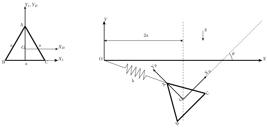
Rectangle $ABCD$ with its centre $G$ and the body axes $x_B$, $y_B$ (left), and the rectangle in the inertial frame $O_1X_1Y_1$ with the spring from $O_1$ to $A$, the vertex $C$ on the horizontal line $y = 5a/4$, the angle $\theta$ and the gravity $g$ (right).
Figure: Rectangle $ABCD$ with its centre $G$ and the body axes $x_B$, $y_B$ (left), and the rectangle in the inertial frame $O_1X_1Y_1$ with the spring from $O_1$ to $A$, the vertex $C$ on the horizontal line $y = 5a/4$, the angle $\theta$ and the gravity $g$ (right). (Problems.pdf, p. 43).
Worked Solution [ Click to Expand ]

Reference Frames, Bases and Degrees of Freedom

  • Physical system: a homogeneous rectangular plate $ABCD$ of mass $m$, side $AB$ of length $a$ and side $AD$ of length $b$, with $b$ equal to $\sqrt3\,a$, moving in a vertical plane. A spring of stiffness $k$ joins the origin $O_1$ to the vertex $A$; the vertex $C$ slides along the horizontal line at height $5a/4$. Gravity acts along $-\mathbf j_1$ (read from the figure).
  • Natural length of the spring: the statement gives none; it is taken as zero, as in the rest of the course (Notes.pdf, Sec. 7.5), so the spring force is $-k$ times the vector from $O_1$ to $A$.
  • Guide: the statement does not mention friction; the line is taken as smooth, so its reaction on $C$ is normal to it, along $\mathbf j_1$.
  • Fixed frame: $S_0\{O_1; \mathbf i_1, \mathbf j_1, \mathbf k_1\}$, with $\mathbf i_1$ horizontal to the right, $\mathbf j_1$ up and $\mathbf k_1$ out of the paper (⊙). It is inertial.
  • Body frame: $S_B\{G; \mathbf i_B, \mathbf j_B, \mathbf k_1\}$ with $\mathbf i_B$ parallel to $AD$ (from $A$ to $D$) and $\mathbf j_B$ parallel to $AB$ (from $A$ to $B$), as in the left figure.
  • Coordinates: the abscissa $x_G$ of $G$ and the angle $\theta$ from $\mathbf i_1$ to $\mathbf i_B$, positive counterclockwise (the figure draws it from the horizontal through $G$ to $Gx_B$). The height $y_G$ follows from the guide.
  • Degrees of freedom: three for a plane motion, minus one for the guide: two, $x_G$ and $\theta$.
  • Unknowns of the dynamics: $x_G(t)$, $\theta(t)$ and the guide reaction $N$; three scalar equations (two force components and one moment component) are needed.
DatumSymbolSI unit
Mass, homogeneous$m$kg
Sides$AB = a$, $AD = b = \sqrt3\,a$m
Spring from $O_1$ to $A$stiffness $k$, zero natural lengthN/m
Guide of $C$horizontal line at height $5a/4$, smoothm
Gravity$g$, along $-\mathbf j_1$m/s$^2$
Initial velocity of $A$ (part b)$u_0\,\mathbf i_1 + v_0\,\mathbf j_1$m/s
Equilibrium angle (part c)$\pi/3$rad

Change of Basis, Position Vectors and Constraint Kinematics

i1 j1 iB jB cos θ sin θ −sin θ cos θ θ θ k1 (⊙) at G
Figure 1. Body basis of the rectangle, turned by $\theta$ about $\mathbf k_1$ (⊙). The axis $\mathbf j_B$ leans to negative $\mathbf i_1$, which gives the minus sign of $[{}_0R_B]$.
Body basis: rotation about k1 by the angle theta Law: simple rotation about the third axis, positive by the right-hand rule Source: Notes.pdf, Eq. 1.20; Notes.pdf, Eq. 1.15; [Lecture 7, Slide 12]

View of the plane with $\mathbf k_1$ out of the paper (⊙), $\mathbf i_1$ to the right and $\mathbf j_1$ up; positive $\theta$ is counterclockwise.

$$\begin{aligned} \mathbf i_B &= \cos\theta\,\mathbf i_1 + \sin\theta\,\mathbf j_1 \quad &\text{(right triangle with hypotenuse 1: adjacent leg along $\mathbf i_1$, opposite leg along $\mathbf j_1$)} \\ \mathbf j_B &= -\sin\theta\,\mathbf i_1 + \cos\theta\,\mathbf j_1 \quad &\text{($\mathbf j_1$ turned counterclockwise about $\mathbf k_1$, out of the paper, leans to negative $\mathbf i_1$)} \\ [{}_0R_B] &= \begin{bmatrix} \cos\theta & -\sin\theta & 0 \cr \sin\theta & \cos\theta & 0 \cr 0 & 0 & 1 \end{bmatrix} \quad &\text{(columns: $\mathbf i_B$, $\mathbf j_B$, $\mathbf k_1$ in $\mathcal B_0$)} \\ \det[{}_0R_B] &= 1\cdot\left(\cos^2\theta + \sin^2\theta\right) = 1 \quad &\text{(expand along the third row)} \\ [{}_0R_B][{}_0R_B]^T &= \begin{bmatrix} \cos^2\theta + \sin^2\theta & \cos\theta\sin\theta - \sin\theta\cos\theta & 0 \cr \sin\theta\cos\theta - \cos\theta\sin\theta & \sin^2\theta + \cos^2\theta & 0 \cr 0 & 0 & 1 \end{bmatrix} = [U] \quad &\text{(row by row products)} \\ \boldsymbol\omega_{B0} &= \dot\theta\,\mathbf k_1, \qquad \boldsymbol\alpha_{B0} = \ddot\theta\,\mathbf k_1 \quad &\text{(single rotation about the fixed axis $\mathbf k_1$; product rule)} \end{aligned}$$
$$\boxed{\mathbf i_B = \cos\theta\,\mathbf i_1 + \sin\theta\,\mathbf j_1, \qquad \mathbf j_B = -\sin\theta\,\mathbf i_1 + \cos\theta\,\mathbf j_1, \qquad \boldsymbol\omega_{B0} = \dot\theta\,\mathbf k_1}$$

Units: the matrix is dimensionless; $\boldsymbol\omega_{B0}$ in $[\mathrm{T^{-1}}]$

Meaning: for $\theta$ equal to $\pi/2$ the long side $AD$ is vertical; for $\theta$ equal to $\pi/3$, as in the figure, $C$ is straight above $G$.

The half diagonal GC

iB jB b/2 = √3 a/2 a/2 rGC |GC| = a rGA = −rGC θ γ β = θ + π/6 γ = π/6 G A B C D
Figure 2. The half diagonal $GC$ has length $a$ and makes the angle $\pi/6$ with $\mathbf i_B$, so its angle from the horizontal is $\beta = \theta + \pi/6$; $A$ is at the opposite end of the same diagonal.
Vector from G to C: the half diagonal Law: position vector as a sum of segments along the body axes; Pythagoras and the addition formulas Source: Notes.pdf, Sec. 7.4; Notes.pdf, Eq. 1.12; Problems.pdf, p. 43

In the right triangle with legs $b/2$ along $\mathbf i_B$ and $a/2$ along $\mathbf j_B$ and hypotenuse $GC$, the angle at $G$ between $\mathbf i_B$ and $GC$ is the one whose tangent is the opposite leg over the adjacent leg.

$$\begin{aligned} \mathbf r_G^C &= \frac b2\,\mathbf i_B + \frac a2\,\mathbf j_B = \frac{\sqrt3}{2}\,a\,\mathbf i_B + \frac12\,a\,\mathbf j_B \quad &\text{(half the sides, from the centre to the corner $C$)} \\ GC &= \sqrt{\frac34\,a^2 + \frac14\,a^2} = a \quad &\text{(Pythagoras: the half diagonal equals $a$)} \\ \tan\gamma &= \frac{a/2}{\sqrt3\,a/2} = \frac{1}{\sqrt3}, \qquad \gamma = \frac{\pi}{6} \quad &\text{(opposite leg over adjacent leg)} \\ \mathbf r_G^C &= a\left[\cos\tfrac{\pi}{6}\left(\cos\theta\,\mathbf i_1 + \sin\theta\,\mathbf j_1\right) + \sin\tfrac{\pi}{6}\left(-\sin\theta\,\mathbf i_1 + \cos\theta\,\mathbf j_1\right)\right] \quad &\text{(rotation box; $\sqrt3/2$ and $1/2$ are the cosine and sine of $\pi/6$)} \\ &= a\left[\cos\left(\theta + \tfrac{\pi}{6}\right)\mathbf i_1 + \sin\left(\theta + \tfrac{\pi}{6}\right)\mathbf j_1\right] \quad &\text{(addition formulas for the cosine and the sine)} \\ \beta &\equiv \theta + \frac{\pi}{6}, \qquad \dot\beta = \dot\theta \quad &\text{(angle of $GC$ from the horizontal; chain rule)} \end{aligned}$$
$$\boxed{\mathbf r_G^C = a\left(\cos\beta\,\mathbf i_1 + \sin\beta\,\mathbf j_1\right), \qquad \mathbf r_G^A = -\mathbf r_G^C, \qquad \beta = \theta + \frac{\pi}{6}}$$

Units: $[\mathrm L]$; angles dimensionless

Meaning: the corners $A$ and $C$ are the two ends of a diagonal of length $2a$ through $G$, which makes the angle $\beta$ with the horizontal. All the geometry of the problem depends on $\theta$ only through $\beta$.

Positions, velocities and accelerations Law: guide constraint on $C$; time derivatives in $S_0$ with the chain rule; velocity field Source: Notes.pdf, Eq. 2.6; Notes.pdf, Eq. 9.3; Notes.pdf, Eq. 9.4; [Lecture 7, Slide 6]
$$\begin{aligned} y_G + a\sin\beta &= \frac54\,a \quad &\text{(height of $C$ fixed by the guide)} \\ \mathbf r_0^G &= x_G\,\mathbf i_1 + \left(\frac54\,a - a\sin\beta\right)\mathbf j_1 \quad &\text{(solve for $y_G$)} \\ \mathbf r_0^A &= \mathbf r_0^G - \mathbf r_G^C = \left(x_G - a\cos\beta\right)\mathbf i_1 + \left(\frac54\,a - 2a\sin\beta\right)\mathbf j_1 \quad &\text{(sum of segments)} \\ \dot y_G &= -a\cos\beta\,\dot\theta \quad &\text{(chain rule: derivative of the sine is the cosine, times $\dot\beta = \dot\theta$)} \\ \ddot y_G &= -a\cos\beta\,\ddot\theta + a\sin\beta\,\dot\theta^2 \quad &\text{(product rule and chain rule)} \\ \mathbf v_0^C &= \mathbf v_0^G + \dot\theta\,\mathbf k_1\times a\left(\cos\beta\,\mathbf i_1 + \sin\beta\,\mathbf j_1\right) \quad &\text{(velocity field from $G$ to $C$)} \\ &= \left(\dot x_G - a\sin\beta\,\dot\theta\right)\mathbf i_1 + \left(-a\cos\beta\,\dot\theta + a\cos\beta\,\dot\theta\right)\mathbf j_1 \quad &\text{($\mathbf k_1\times\mathbf i_1 = \mathbf j_1$, $\mathbf k_1\times\mathbf j_1 = -\mathbf i_1$)} \\ \mathbf v_0^A &= \mathbf v_0^G - \dot\theta\,\mathbf k_1\times\mathbf r_G^C = \left(\dot x_G + a\sin\beta\,\dot\theta\right)\mathbf i_1 - 2a\cos\beta\,\dot\theta\,\mathbf j_1 \quad &\text{(velocity field from $G$ to $A$)} \end{aligned}$$
$$\boxed{\mathbf a_0^G = \ddot x_G\,\mathbf i_1 + \left(a\sin\beta\,\dot\theta^2 - a\cos\beta\,\ddot\theta\right)\mathbf j_1, \qquad \mathbf v_0^C\cdot\mathbf j_1 = 0, \qquad \mathbf v_0^A = \left(\dot x_G + a\sin\beta\,\dot\theta\right)\mathbf i_1 - 2a\cos\beta\,\dot\theta\,\mathbf j_1}$$

Units: $[\mathrm L]$, $[\mathrm{L\,T^{-1}}]$, $[\mathrm{L\,T^{-2}}]$

Meaning: the velocity of $C$ comes out horizontal, which checks that the height of $G$ was written correctly; the vertical motion of $G$ is slaved to the rotation.

Center of Mass and Inertia Tensor

xB yB xB yB dm = dxB dyB b = √3 a a A D C B G
Figure 3. Mass element of the plate for the integrals of the moments of inertia about the axes through $G$.
Part (a): moments of inertia of the rectangle about G Law: definition of the moments and products of inertia of a homogeneous plate; first symmetry theorem Source: Notes.pdf, Eq. 10.11; Notes.pdf, Eq. 10.15; Notes.pdf, Eq. 10.22; Notes.pdf, Sec. 10.5; [Lecture 8, Slide 19]

The centre of mass is the centre of the rectangle: the two midlines are axes of symmetry. In $S_B$ the plate covers the coordinates from $-b/2$ to $b/2$ along $\mathbf i_B$ and from $-a/2$ to $a/2$ along $\mathbf j_B$.

$$\begin{aligned} dm &= \frac{m}{ab}\,dx_B\,dy_B \quad &\text{(homogeneous: mass over area)} \\ I_{x_B} &= \int_{-a/2}^{a/2}\int_{-b/2}^{b/2}\frac{m}{ab}\,y_B^2\,dx_B\,dy_B = \frac{m}{ab}\,b\left[\frac{y_B^3}{3}\right]_{-a/2}^{a/2} \quad &\text{(inner integral in $x_B$ gives $b$; antiderivative)} \\ &= \frac ma\left(\frac{a^3}{24} + \frac{a^3}{24}\right) = \frac{m a^2}{12} \quad &\text{(Barrow with both limits)} \\ I_{y_B} &= \frac{m}{ab}\,a\left[\frac{x_B^3}{3}\right]_{-b/2}^{b/2} = \frac{m b^2}{12} = \frac{3\,m a^2}{12} = \frac{m a^2}{4} \quad &\text{(same steps with $x_B^2$; $b^2 = 3a^2$)} \\ I_{z_B} &= I_{x_B} + I_{y_B} = \frac{m a^2}{12} + \frac{3\,m a^2}{12} = \frac{m a^2}{3} \quad &\text{(flat body: the normal moment is the sum, Eq. 10.22)} \\ P_{x_Bz_B,y_Bz_B} &= \int x_B\,y_B\,dm = \frac{m}{ab}\left[\frac{x_B^2}{2}\right]_{-b/2}^{b/2}\left[\frac{y_B^2}{2}\right]_{-a/2}^{a/2} = 0 \quad &\text{(each bracket vanishes: symmetric limits)} \\ P_{x_By_B,x_Bz_B} &= P_{x_By_B,y_Bz_B} = 0 \quad &\text{(flat body in the plane $z_B = 0$)} \end{aligned}$$
$$\boxed{\bar{\bar I}_G = \frac{m a^2}{12}\begin{bmatrix} 1 & 0 & 0 \cr 0 & 3 & 0 \cr 0 & 0 & 4 \end{bmatrix}_{BB}, \qquad I_G = I_{z_B} = \frac{m a^2}{3}}$$

Units: $[\mathrm M][\mathrm L^2]$

Meaning: the moment about the axis normal to the plate, which governs the plane rotation, is $ma^2/3$; it equals $m$ times the squared half diagonal over three, because the squared half diagonal is $a^2$ here.

Linear Momentum, Angular Momentum and Kinetic Energy

Momentum, angular momentum about G and kinetic energy Law: linear momentum from $G$; angular momentum about $G$ from the inertia tensor; Koenig's decomposition Source: Notes.pdf, Eq. 11.3; Notes.pdf, Eq. 11.12; Notes.pdf, Eq. 11.31; [Lecture 9, Slide 5]; [Lecture 9, Slide 10]
$$\begin{aligned} \mathbf p_0 &= m\,\mathbf v_0^G = m\,\dot x_G\,\mathbf i_1 - m a\cos\beta\,\dot\theta\,\mathbf j_1 \quad &\text{(Eq. 11.3 with the velocity of $G$)} \\ [\mathbf H_{G,0}]_B &= \frac{m a^2}{12}\begin{bmatrix} 1 & 0 & 0 \cr 0 & 3 & 0 \cr 0 & 0 & 4 \end{bmatrix}\begin{bmatrix} 0 \cr 0 \cr \dot\theta \end{bmatrix} = \begin{bmatrix} 0 \cr 0 \cr \tfrac{m a^2}{3}\dot\theta \end{bmatrix} \quad &\text{(Eq. 11.12; row by column products)} \\ T_0 &= \frac12\,m\left(\dot x_G^2 + a^2\cos^2\beta\,\dot\theta^2\right) + \frac12\cdot\frac{m a^2}{3}\,\dot\theta^2 \quad &\text{(Eq. 11.31)} \end{aligned}$$
$$\boxed{\mathbf H_{G,0} = \frac{m a^2}{3}\,\dot\theta\,\mathbf k_1, \qquad T_0 = \frac12\,m\,\dot x_G^2 + \frac12\,m a^2\left(\frac13 + \cos^2\beta\right)\dot\theta^2}$$

Units: kg m$^2$/s and J

Meaning: the guide makes the rotation drag the centre of mass up and down, which adds the term in the squared cosine to the rotational inertia.

Free-Body Diagram and Equations of Motion

guide, height 5a/4 O1 mg N k|r0A| G A B C D θ
Figure 4. Free-body diagram: weight at $G$, smooth guide reaction $N\,\mathbf j_1$ at $C$ (arm $a\cos\beta$ about $G$) and spring force $-k\,\mathbf r_0^A$ at $A$, pointing to $O_1$.
ForcePoint of applicationExpressionKind
Weight$G$$-mg\,\mathbf j_1$applied
Spring$A$$-k\,\mathbf r_0^A = -k(x_A\,\mathbf i_1 + y_A\,\mathbf j_1)$applied (Notes.pdf, Sec. 7.5)
Guide reaction$C$$N\,\mathbf j_1$, $N$ unknownconstraint: smooth, normal to the line
Force equation Law: Newton's second law for the centre of mass of a rigid body Source: Notes.pdf, Eq. 12.8; Notes.pdf, Sec. 7.5; [Lecture 10, Slide 4]
$$\begin{aligned} m\,\mathbf a_0^G &= -mg\,\mathbf j_1 - k\,\mathbf r_0^A + N\,\mathbf j_1 \quad &\text{(Eq. 12.8 with the forces of the table)} \\ m\,\ddot x_G &= -k\left(x_G - a\cos\beta\right) \quad &\text{($\mathbf i_1$ component)} \\ m\left(a\sin\beta\,\dot\theta^2 - a\cos\beta\,\ddot\theta\right) &= N - mg - k\left(\frac54\,a - 2a\sin\beta\right) \quad &\text{($\mathbf j_1$ component with the acceleration of $G$)} \end{aligned}$$
$$\boxed{m\,\ddot x_G = -k\left(x_G - a\cos\beta\right), \qquad N = mg + k\left(\frac54\,a - 2a\sin\beta\right) + m a\left(\sin\beta\,\dot\theta^2 - \cos\beta\,\ddot\theta\right)}$$

Units: N in every term

Meaning: only the spring pushes horizontally; the guide reaction carries the weight and the vertical pull of the spring, plus the force needed to give $G$ its vertical acceleration.

Moment equation about G Law: moment equation about the centre of mass; moments of the spring and guide forces by their determinants Source: Notes.pdf, Eq. 12.13; Notes.pdf, Eq. 12.16; Notes.pdf, Eq. 12.14; [Lecture 10, Slide 5]

The pole is $G$: the weight passes through it, and the extra term of Eq. 12.13 vanishes for the pole $G$.

$$\begin{aligned} \left.\frac{d\mathbf H_{G,0}}{dt}\right|_0 &= \frac{m a^2}{3}\,\ddot\theta\,\mathbf k_1 \quad &\text{(product rule; $\mathbf k_1$ fixed)} \\ \mathbf r_G^A\times\left(-k\,\mathbf r_0^A\right) &= \begin{vmatrix} \mathbf i_1 & \mathbf j_1 & \mathbf k_1 \cr -a\cos\beta & -a\sin\beta & 0 \cr -k x_A & -k y_A & 0 \end{vmatrix} = ka\left(y_A\cos\beta - x_A\sin\beta\right)\mathbf k_1 \quad &\text{(expand along the first row: only $\mathbf k_1$ survives)} \\ y_A\cos\beta - x_A\sin\beta &= \frac54\,a\cos\beta - 2a\sin\beta\cos\beta - x_G\sin\beta + a\cos\beta\sin\beta \quad &\text{(components of $A$)} \\ &= \frac54\,a\cos\beta - a\sin\beta\cos\beta - x_G\sin\beta \quad &\text{(collect)} \\ \mathbf r_G^C\times N\,\mathbf j_1 &= \begin{vmatrix} \mathbf i_1 & \mathbf j_1 & \mathbf k_1 \cr a\cos\beta & a\sin\beta & 0 \cr 0 & N & 0 \end{vmatrix} = N a\cos\beta\,\mathbf k_1 \quad &\text{(expand along the first row)} \\ \frac{m a^2}{3}\,\ddot\theta &= ka\left(\frac54\,a\cos\beta - a\sin\beta\cos\beta - x_G\sin\beta\right) + N a\cos\beta \quad &\text{(Eq. 12.13 at $G$, $\mathbf k_1$ component)} \end{aligned}$$
$$\boxed{\frac{m a^2}{3}\,\ddot\theta = ka\left(\frac54\,a\cos\beta - a\sin\beta\cos\beta - x_G\sin\beta\right) + N a\cos\beta}$$

Units: N m in every term

Meaning: the guide reaction turns the plate with the arm $a\cos\beta$, the horizontal distance from $G$ to $C$; the spring turns it unless its line passes through $G$.

Equations of motion with the reaction eliminated Law: substitution of the vertical force equation into the moment equation Source: Notes.pdf, Eq. 12.8; Notes.pdf, Eq. 12.13; [Lecture 10, Slide 8]
$$\begin{aligned} \frac{m a^2}{3}\,\ddot\theta &= ka\left(\frac54\,a\cos\beta - a\sin\beta\cos\beta - x_G\sin\beta\right) + a\cos\beta\left[mg + \frac54\,ka - 2ka\sin\beta + m a\sin\beta\,\dot\theta^2 - m a\cos\beta\,\ddot\theta\right] \quad &\text{(N from the force box)} \\ m a^2\left(\frac13 + \cos^2\beta\right)\ddot\theta &= m a^2\sin\beta\cos\beta\,\dot\theta^2 + mga\cos\beta + \frac52\,ka^2\cos\beta - 3ka^2\sin\beta\cos\beta - ka\,x_G\sin\beta \quad &\text{(move the term in $\ddot\theta$ to the left; collect the spring terms)} \end{aligned}$$
$$\boxed{\begin{gathered} m\,\ddot x_G + k\left(x_G - a\cos\beta\right) = 0 \\ m a^2\left(\tfrac13 + \cos^2\beta\right)\ddot\theta - m a^2\sin\beta\cos\beta\,\dot\theta^2 = a\cos\beta\left(mg + \tfrac52\,ka - 3ka\sin\beta\right) - ka\,x_G\sin\beta \end{gathered}, \qquad \beta = \theta + \frac{\pi}{6}}$$

Units: N and N m

Meaning: two coupled second-order equations for the two degrees of freedom; the reaction then follows from the force box at every instant.

Part (b): initial conditions and instantaneous axis

Part (b): initial conditions Law: configuration at the initial instant; velocity of $A$ from the kinematics box Source: Notes.pdf, Eq. 9.3; Problems.pdf, p. 43
$$\begin{aligned} \mathbf i_B(0) &= \mathbf j_1 \ \Rightarrow\ \theta(0) = \frac{\pi}{2}, \quad \beta(0) = \frac{2\pi}{3} \quad &\text{($BC$ on the vertical axis; with $\mathbf i_B$ down, $\mathbf j_B$ would point right and $A$ would be at negative $x_1$)} \\ x_C(0) &= x_G(0) + a\cos\tfrac{2\pi}{3} = x_G(0) - \frac a2 = 0 \quad &\text{(C on the axis $O_1Y_1$)} \\ x_G(0) &= \frac a2, \qquad y_G(0) = \frac54\,a - \frac{\sqrt3}{2}\,a \quad &\text{(solve; height from the guide)} \\ u_0\,\mathbf i_1 + v_0\,\mathbf j_1 &= \left(\dot x_G + \frac{\sqrt3}{2}\,a\,\dot\theta\right)\mathbf i_1 + a\,\dot\theta\,\mathbf j_1 \quad &\text{(velocity of $A$ with $\sin\beta = \sqrt3/2$, $\cos\beta = -1/2$)} \\ \dot\theta(0) &= \frac{v_0}{a}, \qquad \dot x_G(0) = u_0 - \frac{\sqrt3}{2}\,v_0 \quad &\text{(equate components)} \end{aligned}$$
$$\boxed{x_G(0) = \frac a2, \qquad \dot x_G(0) = u_0 - \frac{\sqrt3}{2}\,v_0, \qquad \theta(0) = \frac{\pi}{2}, \qquad \dot\theta(0) = \frac{v_0}{a}}$$

Units: m, m/s, rad, rad/s

Meaning: four conditions for two second-order equations; the vertical velocity of $A$ fixes the rate of rotation, because $C$ cannot move vertically and $A$ is $2a\cos\beta$ to the side of it.

i1 j1 O1 guide v0A v0C AI I θ̇ G A B C D
Figure 5. Instantaneous axis at $t = 0$: $I$ lies on $O_1Y_1$, the normal to the horizontal velocity of $C$, at the height $a(\tfrac54 - \sqrt3 + u_0/v_0)$.
Part (b): instantaneous axis of rotation at t = 0 Law: point of zero velocity of a plane motion, from the known velocity of $A$ Source: Notes.pdf, Eq. 9.10; Notes.pdf, Eq. 9.8; [Lecture 7, Slide 9]
$$\begin{aligned} \mathbf{AI} &= \frac{\boldsymbol\omega_{B0}\times\mathbf v_0^A}{\omega_{B0}^2} = \frac{\mathbf k_1\times\left(u_0\,\mathbf i_1 + v_0\,\mathbf j_1\right)}{\dot\theta} \quad &\text{(Eq. 9.10 from $A$)} \\ &= \frac{a}{v_0}\left(u_0\,\mathbf j_1 - v_0\,\mathbf i_1\right) = -a\,\mathbf i_1 + \frac{a\,u_0}{v_0}\,\mathbf j_1 \quad &\text{($\mathbf k_1\times\mathbf i_1 = \mathbf j_1$, $\mathbf k_1\times\mathbf j_1 = -\mathbf i_1$; initial rate)} \\ \mathbf r_0^A(0) &= a\,\mathbf i_1 + \left(\frac54\,a - \sqrt3\,a\right)\mathbf j_1 \quad &\text{(position of $A$ with $\beta = 2\pi/3$, $x_G = a/2$)} \\ \mathbf r_0^I &= \mathbf r_0^A + \mathbf{AI} = \left(\frac54\,a - \sqrt3\,a + \frac{a\,u_0}{v_0}\right)\mathbf j_1 \quad &\text{(add)} \end{aligned}$$
$$\boxed{\text{axis at } t = 0\text{: the line through } \mathbf r_0^I = a\left(\frac54 - \sqrt3 + \frac{u_0}{v_0}\right)\mathbf j_1 \text{ parallel to } \mathbf k_1}$$

Units: $[\mathrm L]$

Meaning: the axis lies on the vertical through $C$, the axis $O_1Y_1$, as it must: $C$ moves horizontally, so the centre of rotation is on the normal to its velocity. If $v_0$ vanishes the plate translates.

Part (c): equilibrium at theta = pi/3

Part (c): position of G and reaction force Law: equilibrium of a rigid body: zero resultant force and zero moment at rest Source: Notes.pdf, Eq. 12.24; Notes.pdf, Eq. 12.25; [Lecture 10, Slide 19]

At $\theta$ equal to $\pi/3$ the angle of the half diagonal is $\beta$ equal to $\pi/2$: $C$ is straight above $G$ and $A$ straight below it.

$$\begin{aligned} 0 &= -k\left(x_G - a\cos\tfrac{\pi}{2}\right) \ \Rightarrow\ x_G = 0 \quad &\text{(horizontal force equation at rest)} \\ y_G &= \frac54\,a - a\sin\tfrac{\pi}{2} = \frac a4 \quad &\text{(guide)} \\ \mathbf r_0^A &= \left(0 - 0\right)\mathbf i_1 + \left(\frac54\,a - 2a\right)\mathbf j_1 = -\frac34\,a\,\mathbf j_1 \quad &\text{(position of $A$)} \\ \frac{m a^2}{3}\cdot 0 &= ka\left(0 - 0 - 0\right) + N a\cdot 0 \quad &\text{(moment equation: every arm is zero because $\cos\beta = 0$ and $x_G = 0$)} \\ N &= mg + k\left(\frac54\,a - 2a\right) = mg - \frac34\,ka \quad &\text{(vertical force equation at rest)} \end{aligned}$$
$$\boxed{\mathbf r_0^G = \frac a4\,\mathbf j_1, \qquad N\,\mathbf j_1 = \left(mg - \frac34\,ka\right)\mathbf j_1}$$

Units: m and N

Meaning: in equilibrium $O_1$, $A$, $G$ and $C$ lie on the vertical axis $O_1Y_1$, so the three forces are vertical and collinear and the moment equation holds for any stiffness. The spring, stretched by $3a/4$, pulls $A$ up; the guide carries the rest of the weight (it pushes up while the stiffness is below $4mg/(3a)$, and must pull down above it).

Part (d): small oscillations with G fixed and C released

Part (d): linearized equation and frequency Law: moment equation about the fixed point $G$; Taylor expansion to first order about the equilibrium; harmonic oscillator Source: Notes.pdf, Eq. 12.13; Notes.pdf, Sec. 14.4; Notes.pdf, Eq. 5.6; [Lecture 6, Slide 15]

With $G$ held at its equilibrium position and $C$ free, the only force with a moment about $G$ is the spring; the support at $G$ acts at the pole.

$$\begin{aligned} x_A &= -a\cos\beta, \qquad y_A = \frac a4 - a\sin\beta \quad &\text{(G fixed at $(0, a/4)$; A at the other end of the half diagonal)} \\ y_A\cos\beta - x_A\sin\beta &= \frac a4\cos\beta - a\sin\beta\cos\beta + a\cos\beta\sin\beta = \frac a4\cos\beta \quad &\text{(the products cancel)} \\ \frac{m a^2}{3}\,\ddot\theta &= \frac{k a^2}{4}\cos\beta \quad &\text{(moment equation about $G$, spring only)} \\ \cos\beta &= \cos\left(\tfrac{\pi}{2} + \phi\right) = -\sin\phi \approx -\phi \quad &\text{(with $\theta = \pi/3 + \phi$; first order)} \\ \frac{m a^2}{3}\,\ddot\phi &= -\frac{k a^2}{4}\,\phi \quad &\text{(the second derivative of the constant is zero)} \\ \ddot\phi + \frac{3k}{4m}\,\phi &= 0 \quad &\text{(divide by the moment of inertia)} \end{aligned}$$
$$\boxed{\ddot\phi + \frac{3k}{4m}\,\phi = 0, \qquad \Omega = \sqrt{\frac{3k}{4m}} = \frac{\sqrt3}{2}\sqrt{\frac km} \approx 0.866\,\sqrt{\frac km}}$$

Units: $[\mathrm{M\,T^{-2}}]/[\mathrm M] = [\mathrm{T^{-2}}]$; the frequency in rad/s

Meaning: the exact equation is that of a pendulum, with the sine of the perturbation in place of the perturbation; the equilibrium is stable and the small oscillations are harmonic.

Answers and Checks

AskedAnswer
(a) Moment of inertia about $G$$I_G = \tfrac{ma^2}{3}$ (normal axis); tensor $\tfrac{ma^2}{12}\,\mathrm{diag}(1, 3, 4)$ in $\mathcal B_B$
(b) Equations of motion$m\ddot x_G + k(x_G - a\cos\beta) = 0$; $ma^2(\tfrac13 + \cos^2\beta)\ddot\theta - ma^2\sin\beta\cos\beta\,\dot\theta^2 = a\cos\beta(mg + \tfrac52 ka - 3ka\sin\beta) - ka\,x_G\sin\beta$, with $\beta = \theta + \pi/6$; reaction $N = mg + k(\tfrac54 a - 2a\sin\beta) + ma(\sin\beta\,\dot\theta^2 - \cos\beta\,\ddot\theta)$
(b) Initial conditions$x_G = \tfrac a2$, $\dot x_G = u_0 - \tfrac{\sqrt3}{2}v_0$, $\theta = \tfrac{\pi}{2}$, $\dot\theta = \tfrac{v_0}{a}$
(b) Axis at $t = 0$normal to the plane through $(0, a(\tfrac54 - \sqrt3 + \tfrac{u_0}{v_0}))$
(c) Equilibrium at $\pi/3$$G$ at $(0, \tfrac a4)$; reaction $(mg - \tfrac34 ka)\,\mathbf j_1$ on $C$
(d) Frequency with $G$ fixed, $C$ free$\Omega = \sqrt{3k/(4m)}$

Problems.pdf prints no answer for this problem (see Problem Set - Rigid Body Official Key), so the results are checked by consistency and limiting cases.

Check: the guide does no work and the energy is conserved Law: power of a constraint force on a point whose velocity is normal to it; conservation of the mechanical energy Source: Notes.pdf, Eq. 12.27; Notes.pdf, Eq. 12.33; Notes.pdf, Eq. 12.34; [Lecture 10, Slide 18]
$$\begin{aligned} N\,\mathbf j_1\cdot\mathbf v_0^C &= N\left(\mathbf v_0^C\cdot\mathbf j_1\right) = 0 \quad &\text{(the velocity of $C$ is horizontal: kinematics box)} \\ E &= T_0 + mg\,y_G + \frac12\,k\left(x_A^2 + y_A^2\right) \quad &\text{(weight and spring of zero length are conservative)} \\ E &= \frac12\,m\,\dot x_G^2 + \frac12\,m a^2\left(\tfrac13 + \cos^2\beta\right)\dot\theta^2 + mg\left(\tfrac54\,a - a\sin\beta\right) + \frac k2\left[\left(x_G - a\cos\beta\right)^2 + \left(\tfrac54\,a - 2a\sin\beta\right)^2\right] \quad &\text{(positions of $G$ and $A$)} \end{aligned}$$
$$\boxed{E = \text{constant (a first integral of the two equations of motion)}}$$

Units: J

Meaning: differentiating this energy with the chain rule and substituting the two equations of motion gives zero identically (checked symbolically), which confirms the reduced equation of the rotation.

Limiting cases and consistency:

  • Without spring. With zero stiffness the horizontal equation says that $G$ moves at constant horizontal speed, and the rotation equation becomes that of a plate hanging from the sliding point $C$. Linearized about the hanging position ($C$ above $G$), it gives the squared frequency $3g/a$: the weight times the distance $GC$, which is $a$, over the moment of inertia about $G$, $ma^2/3$. That is the known result for a pendulum whose pivot slides freely, with the moment of inertia about $G$ in place of the one about the pivot.
  • Equilibrium alignment. At the equilibrium of part (c) the four points $O_1$, $A$, $G$ and $C$ are on one vertical line; the statement figure draws the configuration schematically (read from the figure: $G$ appears to the right of $O_1Y_1$), but the horizontal force balance requires the spring to be vertical, which puts $G$ on that axis.
  • Part (d). Only the part of the spring force due to the segment $O_1G$ has a moment about the fixed $G$ (the part along $GA$ has no arm), so the restoring moment per radian is the stiffness times the length $O_1G$, $a/4$, times the length $GA$, $a$: that is the coefficient $ka^2/4$ found above. It does not depend on $g$, because the weight acts at the fixed point.
  • Dimensions. Force equations in N, moment equations in N m, frequencies in rad/s.

Interactive geometry simulator: it needs JavaScript. The figures above show the same geometry.

Problem RB 10

Firedoor motion

Original statement · Problems.pdf, p. 44
Group D: Dynamics

A heavy fire door is a rectangular plate with mass $m$. The door is suspended from the ceiling by two rigid links with negligible mass. The door is also tied to the wall by a cable. In case of an emergency, this cable is severed and the door swings under the restraint of the rigid links. Derive the first-order differential equation of motion that governs the angle of inclination $\theta$ of the rigid links. Also derive the expressions for the forces exerted by the links on the plate.
Fire door of height $h$ and width $b$ hung from the ceiling by two rigid links of length $L$ at the points $A$ and $B$, with the angle $\theta$ measured from the vertical, and the cable to the wall at the right.
Figure: Fire door of height $h$ and width $b$ hung from the ceiling by two rigid links of length $L$ at the points $A$ and $B$, with the angle $\theta$ measured from the vertical, and the cable to the wall at the right. (Problems.pdf, p. 44).
Worked Solution [ Click to Expand ]

Reference Frames, Bases and Degrees of Freedom

  • Physical system: a heavy rectangular plate (the door) of mass $m$ and height $h$, moving in a vertical plane. It hangs from the ceiling by two rigid massless links of length $L$, pinned to the ceiling at $O_A$ and $O_B$ and to the top edge of the door at $A$ and $B$. The cable to the wall is cut at the initial instant and plays no part afterwards.
  • Geometry read from the figure: the two ceiling pins are a distance $b$ apart, the same as $A$ and $B$, and the links are drawn parallel; $A$ and $B$ lie on the top edge, symmetric about the vertical midline of the door (the door is slightly wider than $b$). The centre of mass $G$ is the centre of the plate, a depth $h/2$ below the top edge, straight below the midpoint of $AB$.
  • Pins: smooth, so each link carries only a force along its own line (proved in the free-body section); the force is called a tension, positive when it pulls the door towards the ceiling.
  • Fixed frame: $S_0\{O_A; \mathbf i, \mathbf j, \mathbf k\}$ with origin at the ceiling pin of the left link, $\mathbf i$ horizontal to the right (towards the wall), $\mathbf j$ up and $\mathbf k$ out of the paper (⊙). It is inertial.
  • Body frame: $S_B\{G; \mathbf i_B, \mathbf j_B, \mathbf k\}$ attached to the door, with $\mathbf i_B$ along the top edge from $A$ to $B$ and $\mathbf j_B$ up along the side.
  • Coordinate: the angle $\theta$ of the links from the downward vertical, positive when the lower ends lie to the right of the ceiling pins, as drawn (door pushed towards the wall).
  • Degrees of freedom: a plane rigid body has three; each link fixes the distance from a body point to a fixed point, which removes one each. One degree of freedom remains, $\theta$ (the door turns out not to rotate, see the next section).
  • Unknowns of the dynamics: $\theta(t)$ and the two link tensions $T_A$ and $T_B$; three scalar equations are needed: two force components and one moment component.
DatumSymbolSI unit
Mass of the door, homogeneous$m$kg
Height of the door$h$m
Distance between the pins (ceiling and door)$b$m
Length of each link, massless$L$m
Gravity$g$, along $-\mathbf j$m/s$^2$
Initial angle when the cable is cut (not given; used only for the link forces)$\theta_0$, at restrad

Change of Basis, Position Vectors and Constraint Kinematics

θ L eL b iB −L eL −b i OA OB A B k (⊙)
Figure 1. The ceiling pins, the two links of length $L$ and the top edge $AB$ form a parallelogram, so $AB$ stays parallel to the ceiling: the door translates and $\boldsymbol\omega_{B0} = \mathbf 0$.
The links form a parallelogram: the door does not rotate Law: constraint of a rigid link (fixed distance between its two pins); vector sum around a closed loop Source: Notes.pdf, Sec. 9.3; Notes.pdf, Eq. 9.3; Problems.pdf, p. 44

Call $\mathbf e_L$ the unit vector along the left link, from $O_A$ to $A$. Going around the loop $O_A \to A \to B \to O_B \to O_A$ the vectors add to zero.

$$\begin{aligned} \overrightarrow{O_AA} + \overrightarrow{AB} + \overrightarrow{BO_B} + \overrightarrow{O_BO_A} &= \mathbf 0 \quad &\text{(closed loop)} \\ L\,\mathbf e_L + b\,\mathbf i_B - \overrightarrow{O_BB} - b\,\mathbf i &= \mathbf 0 \quad &\text{(lengths of the links and of the two pin spacings)} \\ \overrightarrow{O_BB} &= L\,\mathbf e_L + b\left(\mathbf i_B - \mathbf i\right) \quad &\text{(solve for the right link)} \\ \left\lvert\overrightarrow{O_BB}\right\rvert^2 &= L^2 + 2Lb\,\mathbf e_L\cdot(\mathbf i_B - \mathbf i) + b^2\left\lvert\mathbf i_B - \mathbf i\right\rvert^2 \quad &\text{(square the previous row)} \\ 0 &= b\left\lvert\mathbf i_B - \mathbf i\right\rvert^2 + 2L\,\mathbf e_L\cdot(\mathbf i_B - \mathbf i) \quad &\text{(impose the right link length, $\lvert\overrightarrow{O_BB}\rvert = L$, subtract $L^2$ and divide by $b$)} \\ \mathbf i_B &= \mathbf i \quad &\text{(this root keeps the door parallel to the ceiling, as drawn; the other root is the crossed four-bar branch, which is not reached from the figure)} \\ \overrightarrow{O_BB} &= L\,\mathbf e_L \quad &\text{(put $\mathbf i_B = \mathbf i$ in the third row of the development)} \\ \boldsymbol\omega_{B0} &= \mathbf 0, \qquad \boldsymbol\alpha_{B0} = \mathbf 0 \quad &\text{($\mathbf i_B$ keeps its direction at every instant)} \end{aligned}$$
$$\boxed{\mathbf i_B = \mathbf i, \qquad \mathbf j_B = \mathbf j, \qquad \boldsymbol\omega_{B0} = \mathbf 0}$$

Units: dimensionless basis; $\boldsymbol\omega_{B0}$ in $[\mathrm{T^{-1}}]$

Meaning: with equal links and equal pin spacings the quadrilateral $O_A A B O_B$ is a parallelogram, so the top edge stays parallel to the ceiling: the door moves in curvilinear translation and every point of it describes a circle of radius $L$.

Link basis: the right triangle of the link Law: projection of a unit vector on two perpendicular axes; rotation about the axis normal to the plane Source: Notes.pdf, Eq. 1.20; Notes.pdf, Eq. 1.15; [Lecture 7, Slide 12]

The left link is the hypotenuse, of length $L$, of a right triangle whose horizontal leg (opposite to $\theta$) is $L\sin\theta$ and whose vertical leg (adjacent to $\theta$, measured from the downward vertical) is $L\cos\theta$. Define the unit vector $\mathbf e_n$ along the link from the door to the ceiling and the unit vector $\mathbf e_t$ normal to it, in the sense of increasing $\theta$. View with $\mathbf k$ out of the paper (⊙): $\mathbf e_t$ is $\mathbf i$ turned counterclockwise by $\theta$, and $\mathbf e_n$ is $\mathbf j$ turned by the same angle.

$$\begin{aligned} \overrightarrow{O_AA} &= L\sin\theta\,\mathbf i - L\cos\theta\,\mathbf j \quad &\text{(opposite leg to the right, adjacent leg downwards)} \\ \mathbf e_t &= \cos\theta\,\mathbf i + \sin\theta\,\mathbf j \quad &\text{(hypotenuse 1: adjacent leg along $\mathbf i$, opposite leg along $\mathbf j$)} \\ \mathbf e_n &= -\sin\theta\,\mathbf i + \cos\theta\,\mathbf j \quad &\text{($\mathbf j$ turned counterclockwise about $\mathbf k$, out of the paper, leans to negative $\mathbf i$)} \\ \det\begin{bmatrix} \cos\theta & -\sin\theta \cr \sin\theta & \cos\theta \end{bmatrix} &= \cos^2\theta + \sin^2\theta = 1 \quad &\text{(columns $\mathbf e_t$, $\mathbf e_n$ in $\{\mathbf i, \mathbf j\}$; orthonormal and right-handed)} \\ \mathbf e_t\cdot\mathbf e_n &= -\cos\theta\sin\theta + \sin\theta\cos\theta = 0 \quad &\text{(product of the matrix by its transpose gives the identity)} \\ \mathbf j &= \sin\theta\,\mathbf e_t + \cos\theta\,\mathbf e_n \quad &\text{(inverse change: rows of the matrix)} \\ \frac{d\mathbf e_t}{dt} &= -\sin\theta\,\dot\theta\,\mathbf i + \cos\theta\,\dot\theta\,\mathbf j = \dot\theta\,\mathbf e_n \quad &\text{(chain rule; $\mathbf i$, $\mathbf j$ fixed)} \\ \frac{d\mathbf e_n}{dt} &= -\cos\theta\,\dot\theta\,\mathbf i - \sin\theta\,\dot\theta\,\mathbf j = -\dot\theta\,\mathbf e_t \quad &\text{(chain rule)} \end{aligned}$$
$$\boxed{\mathbf e_t = \cos\theta\,\mathbf i + \sin\theta\,\mathbf j, \qquad \mathbf e_n = -\sin\theta\,\mathbf i + \cos\theta\,\mathbf j, \qquad \overrightarrow{O_AA} = -L\,\mathbf e_n}$$

Units: $[\mathrm L]$ for the position, unit vectors dimensionless

Meaning: the link points from the ceiling down to the door along $-\mathbf e_n$; the derivatives of the two unit vectors are those of a basis turning at the rate of the links, which is not the rate of the door (zero).

i j k (⊙) at OA θ L cos θ L sin θ L i j et en θ θ b/2 h/2 v0G = Lθ̇ et G A
Figure 2. Link of length $L$ as the hypotenuse: legs $L\sin\theta$ (horizontal) and $L\cos\theta$ (vertical). $\mathbf e_t$ and $\mathbf e_n$ are $\mathbf i$ and $\mathbf j$ turned by $\theta$ about $\mathbf k$ (⊙); $G$ moves on a circle of radius $L$.
Position, velocity and acceleration of G Law: position vector as a sum of segments; time derivatives in $S_0$ with the chain and product rules Source: Notes.pdf, Eq. 2.6; Notes.pdf, Eq. 9.3; [Lecture 7, Slide 6]
$$\begin{aligned} \mathbf r_0^G &= \overrightarrow{O_AA} + \overrightarrow{AG} = L\sin\theta\,\mathbf i - L\cos\theta\,\mathbf j + \frac b2\,\mathbf i - \frac h2\,\mathbf j \quad &\text{(link, then half the pin spacing to the right and half the height down)} \\ \mathbf r_0^G &= \left(L\sin\theta + \frac b2\right)\mathbf i - \left(L\cos\theta + \frac h2\right)\mathbf j \quad &\text{(collect)} \\ \mathbf v_0^G &= L\cos\theta\,\dot\theta\,\mathbf i + L\sin\theta\,\dot\theta\,\mathbf j = L\,\dot\theta\,\mathbf e_t \quad &\text{(chain rule; $b$, $h$, $L$ constant)} \\ \mathbf a_0^G &= L\,\ddot\theta\,\mathbf e_t + L\,\dot\theta\,\frac{d\mathbf e_t}{dt} \quad &\text{(product rule)} \\ &= L\,\ddot\theta\,\mathbf e_t + L\,\dot\theta^2\,\mathbf e_n \quad &\text{(derivative of $\mathbf e_t$ from the link box)} \\ \mathbf v_0^A &= \mathbf v_0^G + \boldsymbol\omega_{B0}\times\mathbf r_G^A = \mathbf v_0^G \quad &\text{(velocity field with zero angular velocity: all points move alike)} \end{aligned}$$
$$\boxed{\mathbf r_0^G = \left(L\sin\theta + \frac b2\right)\mathbf i - \left(L\cos\theta + \frac h2\right)\mathbf j, \qquad \mathbf v_0^G = L\,\dot\theta\,\mathbf e_t, \qquad \mathbf a_0^G = L\,\ddot\theta\,\mathbf e_t + L\,\dot\theta^2\,\mathbf e_n}$$

Units: $[\mathrm L]$, $[\mathrm{L\,T^{-1}}]$, $[\mathrm{L\,T^{-2}}]$

Meaning: $G$ moves on a circle of radius $L$ centred a distance $b/2$ to the right of $O_A$ and $h/2$ below it; its acceleration has a tangential part and a centripetal part pointing along the links, towards the ceiling.

Center of Mass and Inertia Tensor

x′ y′ A rGA B rGB x′ y′ dm b h w G
Figure 3. Centre of mass of the door at the centre of the rectangle; the arms to the pins are $\mathbf r_G^A = -\tfrac b2\,\mathbf i + \tfrac h2\,\mathbf j$ and $\mathbf r_G^B = \tfrac b2\,\mathbf i + \tfrac h2\,\mathbf j$.
Centre of mass of the door Law: definition of the centre of mass of a homogeneous plate; symmetric limits Source: Notes.pdf, Eq. 10.6; Notes.pdf, Eq. 10.8; Notes.pdf, Sec. 10.3; [Lecture 8, Slide 9]

Take provisional axes $x'$, $y'$ through the centre of the rectangle, parallel to $\mathbf i_B$ and $\mathbf j_B$; call $w$ the width of the door (not given: read from the figure it is slightly larger than $b$). The plate covers $x'$ from $-w/2$ to $w/2$ and $y'$ from $-h/2$ to $h/2$.

$$\begin{aligned} dm &= \frac{m}{w h}\,dx'\,dy' \quad &\text{(homogeneous: mass over area)} \\ \int x'\,dm &= \frac{m}{wh}\,h\left[\frac{x'^2}{2}\right]_{-w/2}^{w/2} = \frac{m}{w}\left(\frac{w^2}{8} - \frac{w^2}{8}\right) = 0 \quad &\text{(inner integral in $y'$ gives $h$; Barrow with both limits)} \\ \int y'\,dm &= \frac{m}{wh}\,w\left[\frac{y'^2}{2}\right]_{-h/2}^{h/2} = \frac{m}{h}\left(\frac{h^2}{8} - \frac{h^2}{8}\right) = 0 \quad &\text{(same steps)} \\ \mathbf r_G^A &= -\frac b2\,\mathbf i + \frac h2\,\mathbf j, \qquad \mathbf r_G^B = \frac b2\,\mathbf i + \frac h2\,\mathbf j \quad &\text{(pins on the top edge, symmetric about the midline: read from the figure)} \end{aligned}$$
$$\boxed{G \text{ at the centre of the plate}, \qquad \mathbf r_G^A = -\frac b2\,\mathbf i + \frac h2\,\mathbf j, \qquad \mathbf r_G^B = \frac b2\,\mathbf i + \frac h2\,\mathbf j}$$

Units: $[\mathrm M\,\mathrm L]$ for the first moments, $[\mathrm L]$ for the arms

Meaning: the first moments about the centre vanish, so $G$ is the centre of the rectangle; the arms from $G$ to the two pins are mirror images.

The inertia tensor of the door about $G$ is not needed: the angular momentum about $G$ is the tensor applied to the angular velocity, which is zero (see the next box), whatever the moments of inertia are. The width $w$ therefore never enters the answer.

Linear Momentum, Angular Momentum and Kinetic Energy

Momentum, angular momentum about G and kinetic energy Law: linear momentum from $G$; angular momentum about $G$ from the inertia tensor; kinetic energy decomposed at $G$ Source: Notes.pdf, Eq. 11.3; Notes.pdf, Eq. 11.12; Notes.pdf, Eq. 11.31; [Lecture 9, Slide 5]; [Lecture 9, Slide 9]
$$\begin{aligned} \mathbf p_0 &= m\,\mathbf v_0^G = m L\,\dot\theta\,\mathbf e_t \quad &\text{(Eq. 11.3)} \\ \mathbf H_{G,0} &= \bar{\bar I}_G\cdot\boldsymbol\omega_{B0} = \bar{\bar I}_G\cdot\mathbf 0 = \mathbf 0 \quad &\text{(Eq. 11.12; translation)} \\ T_0 &= \frac12\,m\left(v_0^G\right)^2 + \frac12\,\boldsymbol\omega_{B0}\cdot\bar{\bar I}_G\cdot\boldsymbol\omega_{B0} = \frac12\,m L^2\dot\theta^2 + 0 \quad &\text{(Eq. 11.31; $\mathbf e_t$ is a unit vector)} \end{aligned}$$
$$\boxed{\mathbf p_0 = m L\,\dot\theta\,\mathbf e_t, \qquad \mathbf H_{G,0} = \mathbf 0, \qquad T_0 = \frac12\,m L^2\dot\theta^2}$$

Units: kg m/s, kg m$^2$/s, J

Meaning: the door carries the kinetic energy of a point mass $m$ at the end of a pendulum of length $L$; it has no angular momentum about its own centre of mass.

Free-Body Diagram and Equations of Motion

Each massless link pulls along its own line Law: force and moment equations of a body of zero mass, with the pin forces at its two ends Source: Notes.pdf, Eq. 12.8; Notes.pdf, Eq. 12.13; [Lecture 10, Slide 4]

Isolate the left link: the ceiling pin applies $\mathbf F_1$ at $O_A$, the door applies $\mathbf F_2$ at $A$; smooth pins apply no torque, and the link has no weight.

$$\begin{aligned} \mathbf F_1 + \mathbf F_2 &= 0\cdot\mathbf a_0^{G_\ell} = \mathbf 0 \quad &\text{(Eq. 12.8 with zero mass)} \\ \overrightarrow{O_AA}\times\mathbf F_2 &= \left.\frac{d\mathbf H_{O_A,0}}{dt}\right|_0 = \mathbf 0 \quad &\text{(Eq. 12.13 about the fixed pin; zero mass, zero angular momentum)} \\ \mathbf F_2 &\parallel \overrightarrow{O_AA} \quad &\text{(a vector product of non-zero vectors vanishes only if they are parallel)} \end{aligned}$$
$$\boxed{\text{force of the left link on the door: } T_A\,\mathbf e_n \text{ at } A, \qquad \text{right link: } T_B\,\mathbf e_n \text{ at } B}$$

Units: N

Meaning: by the third law the door receives the opposite of the force it applies to the link; it lies along the link, and $\mathbf e_n$ points from the door towards the ceiling, so positive $T_A$ and $T_B$ are tensions. The right link is parallel to the left one, so its force is along the same $\mathbf e_n$.

TA A TB B mg G et en link basis
Figure 4. Free-body diagram: weight $-mg\,\mathbf j$ at $G$ and the link forces $T_A\,\mathbf e_n$ at $A$ and $T_B\,\mathbf e_n$ at $B$, along the links (two-force members); for $\theta \gt 0$ the left link pulls harder.
ForcePoint of applicationExpressionKind
Weight$G$$-mg\,\mathbf j = -mg(\sin\theta\,\mathbf e_t + \cos\theta\,\mathbf e_n)$applied
Left link$A$$T_A\,\mathbf e_n$, $T_A$ unknownconstraint (two-force member)
Right link$B$$T_B\,\mathbf e_n$, $T_B$ unknownconstraint (two-force member)
Force equation in the link basis Law: Newton's second law for the centre of mass of a rigid body Source: Notes.pdf, Eq. 12.8; [Lecture 10, Slide 4]
$$\begin{aligned} m\left(L\,\ddot\theta\,\mathbf e_t + L\,\dot\theta^2\,\mathbf e_n\right) &= \left(T_A + T_B\right)\mathbf e_n - mg\left(\sin\theta\,\mathbf e_t + \cos\theta\,\mathbf e_n\right) \quad &\text{(Eq. 12.8 with the forces of the table)} \\ m L\,\ddot\theta &= -mg\sin\theta \quad &\text{($\mathbf e_t$ component: the links have no component along $\mathbf e_t$)} \\ m L\,\dot\theta^2 &= T_A + T_B - mg\cos\theta \quad &\text{($\mathbf e_n$ component)} \end{aligned}$$
$$\boxed{\ddot\theta + \frac gL\sin\theta = 0, \qquad T_A + T_B = m\left(g\cos\theta + L\,\dot\theta^2\right)}$$

Units: $[\mathrm{T^{-2}}]$ in the first equation ($g/L$ in s$^{-2}$); N in the second

Meaning: the door swings exactly like a simple pendulum of length $L$, independently of its size and mass; the sum of the tensions carries the normal component of the weight plus the centripetal force.

Moment equation about G Law: moment equation about the centre of mass; moments of the link forces by their determinants Source: Notes.pdf, Eq. 12.13; Notes.pdf, Eq. 12.14; Notes.pdf, Eq. 12.16; [Lecture 10, Slide 5]

The pole is $G$: the extra term of Eq. 12.13 vanishes for the pole $G$, and the weight has no moment about it. The components of $\mathbf e_n$ in $\{\mathbf i, \mathbf j\}$ are $-\sin\theta$ and $\cos\theta$.

$$\begin{aligned} \left.\frac{d\mathbf H_{G,0}}{dt}\right|_0 &= \mathbf 0 \quad &\text{(angular momentum identically zero)} \\ \mathbf r_G^A\times T_A\,\mathbf e_n &= \begin{vmatrix} \mathbf i & \mathbf j & \mathbf k \cr -b/2 & h/2 & 0 \cr -T_A\sin\theta & T_A\cos\theta & 0 \end{vmatrix} = T_A\left(-\frac b2\cos\theta + \frac h2\sin\theta\right)\mathbf k \quad &\text{(expand along the first row: only $\mathbf k$ survives)} \\ \mathbf r_G^B\times T_B\,\mathbf e_n &= \begin{vmatrix} \mathbf i & \mathbf j & \mathbf k \cr b/2 & h/2 & 0 \cr -T_B\sin\theta & T_B\cos\theta & 0 \end{vmatrix} = T_B\left(\frac b2\cos\theta + \frac h2\sin\theta\right)\mathbf k \quad &\text{(expand along the first row)} \\ 0 &= T_A\left(h\sin\theta - b\cos\theta\right) + T_B\left(h\sin\theta + b\cos\theta\right) \quad &\text{(Eq. 12.13 at $G$, $\mathbf k$ component, times 2)} \\ 0 &= \left(T_A + T_B\right)h\sin\theta + \left(T_B - T_A\right)b\cos\theta \quad &\text{(regroup)} \end{aligned}$$
$$\boxed{T_A - T_B = \left(T_A + T_B\right)\frac hb\tan\theta}$$

Units: N m in every term before dividing by $b\cos\theta$

Meaning: the door cannot rotate, so the two link forces must have no net moment about $G$; when the links lean ($\theta$ positive) the left link must pull harder.

Link forces Law: solution of the two linear equations for the tensions Source: Notes.pdf, Eq. 12.8; Notes.pdf, Eq. 12.13; [Lecture 10, Slide 8]
$$\begin{aligned} T_A &= \frac12\left[\left(T_A + T_B\right) + \left(T_A - T_B\right)\right] = \frac12\left(T_A + T_B\right)\left(1 + \frac hb\tan\theta\right) \quad &\text{(half the sum plus half the difference)} \\ T_B &= \frac12\left[\left(T_A + T_B\right) - \left(T_A - T_B\right)\right] = \frac12\left(T_A + T_B\right)\left(1 - \frac hb\tan\theta\right) \quad &\text{(half the sum minus half the difference)} \end{aligned}$$
$$\boxed{T_A = \frac m2\left(g\cos\theta + L\,\dot\theta^2\right)\left(1 + \frac hb\tan\theta\right), \qquad T_B = \frac m2\left(g\cos\theta + L\,\dot\theta^2\right)\left(1 - \frac hb\tan\theta\right)}$$

Units: kg times m/s$^2$: N

Meaning: at $\theta$ equal to zero each link carries half the load. The right link goes slack (and the model with taut links fails) if the tangent of the angle exceeds the ratio of the pin spacing to the height.

First-order equation of motion

First integral of the equation of motion Law: multiplication by the rate of the angle and integration in time (chain rule and Barrow's rule) Source: Notes.pdf, Eq. 12.30; Notes.pdf, Eq. 12.33; [Lecture 10, Slide 18]
$$\begin{aligned} \dot\theta\,\ddot\theta + \frac gL\sin\theta\,\dot\theta &= 0 \quad &\text{(multiply the equation of motion by the rate of the angle)} \\ \frac{d}{dt}\left(\frac12\,\dot\theta^2\right) &= \dot\theta\,\ddot\theta, \qquad \frac{d}{dt}\left(-\cos\theta\right) = \sin\theta\,\dot\theta \quad &\text{(chain rule on each term)} \\ \frac{d}{dt}\left(\frac12\,\dot\theta^2 - \frac gL\cos\theta\right) &= 0 \quad &\text{(sum of the two exact derivatives)} \\ \left[\frac12\,\dot\theta^2 - \frac gL\cos\theta\right]_0^t &= 0 \quad &\text{(integrate from the initial instant; Barrow's rule)} \\ \frac L2\,\dot\theta^2 - g\cos\theta &= \frac L2\,\dot\theta_0^2 - g\cos\theta_0 \equiv C \quad &\text{(multiply by $L$; both limits substituted)} \end{aligned}$$
$$\boxed{\frac{L\,\dot\theta^2}{2} - g\cos\theta = C, \qquad C = -g\cos\theta_0 \text{ if released from rest at } \theta_0}$$

Units: $[\mathrm L][\mathrm{T^{-2}}] = [\mathrm{L\,T^{-2}}]$ for both terms (energy per unit mass and length)

Meaning: this is the energy integral of the door divided by $mL$: with the potential energy of the weight, the energy $\tfrac12 mL^2\dot\theta^2 - mg(L\cos\theta + h/2)$ is constant, because the link forces are normal to the velocity of their points of application.

Link forces as functions of the angle (release from rest) Law: substitution of the first integral in the link forces Source: Notes.pdf, Eq. 12.8; Notes.pdf, Eq. 12.30
$$\begin{aligned} L\,\dot\theta^2 &= 2g\left(\cos\theta - \cos\theta_0\right) \quad &\text{(first integral with $C = -g\cos\theta_0$)} \\ T_A + T_B &= m\left(g\cos\theta + 2g\cos\theta - 2g\cos\theta_0\right) = mg\left(3\cos\theta - 2\cos\theta_0\right) \quad &\text{(sum of the tensions)} \end{aligned}$$
$$\boxed{T_{A,B} = \frac{mg}{2}\left(3\cos\theta - 2\cos\theta_0\right)\left(1 \pm \frac hb\tan\theta\right)}$$

Units: N

Meaning: at the release ($\theta$ equal to $\theta_0$) the sum of the tensions drops to $mg\cos\theta_0$; at the bottom it reaches $mg(3 - 2\cos\theta_0)$, more than the weight, because of the centripetal force.

Answers and Checks

AskedAnswer
Kinematicscurvilinear translation: $\boldsymbol\omega_{B0} = \mathbf 0$; $\mathbf v_0^G = L\dot\theta\,\mathbf e_t$
First-order equation of motion$\tfrac12 L\dot\theta^2 - g\cos\theta = C$ (from $\ddot\theta + \tfrac gL\sin\theta = 0$); $C = -g\cos\theta_0$ for release from rest
Force of the left link on the door (at $A$)$T_A\,\mathbf e_n$, $T_A = \tfrac m2(g\cos\theta + L\dot\theta^2)(1 + \tfrac hb\tan\theta)$
Force of the right link on the door (at $B$)$T_B\,\mathbf e_n$, $T_B = \tfrac m2(g\cos\theta + L\dot\theta^2)(1 - \tfrac hb\tan\theta)$
Unit vector along the links$\mathbf e_n = -\sin\theta\,\mathbf i + \cos\theta\,\mathbf j$ (from the door to the ceiling)

Check against the official key: Problems.pdf (p. 79, see Problem Set - Rigid Body Official Key) prints the first-order equation of motion, with the constant $C$ fixed by the initial conditions. It is the boxed first integral above, term by term: match. The key prints no link forces.

QuantityOfficial keyThis solution
Equation of motion$L\dot\theta^2/2 - g\cos\theta = C$$\tfrac12 L\dot\theta^2 - g\cos\theta = C$

Limiting cases and consistency:

  • Small swings. For a small angle the sine is replaced by the angle and the door oscillates with the angular frequency of a simple pendulum, the square root of $g/L$, whatever its height and width: in translation the door behaves as a point mass at $G$ (Notes.pdf, Eq. 5.6; [Lecture 6, Slide 15]).
  • Vertical links. At $\theta$ equal to zero the two tensions are equal, each one half of the weight plus the centripetal force: the symmetric case.
  • Moment balance. About $G$ the horizontal components of the two tensions (both to the left, total $(T_A + T_B)\sin\theta$) act with the arm $h/2$ above $G$ and tend to turn the door; the unequal vertical components with arms $\mp b/2$ cancel that moment. Checked symbolically: the three equations solved together give the same tensions.
  • Energy. The links do no work: each force is along $\mathbf e_n$ while its point moves along $\mathbf e_t$. Differentiating the boxed first integral returns the equation of motion.
  • Dimensions. The equation of motion in s$^{-2}$, the first integral in m/s$^2$, the forces in N.

Interactive geometry simulator: it needs JavaScript. The figures above show the same geometry.

Problem RB 24

Lagrange's top (Heavy axisymmetric pegtop)

Original statement · Problems.pdf, p. 54
Group D: DynamicsIn-Class Session 21

In this problem, we are going to study the motion of a heavy, axisymmetric pegtop of mass $m$. We will assume that during the precession, nutation and spin of the pegtop, the vertex $O$ of the pegtop remains fixed at the origin of the inertial reference frame $Oxyz$. The distance $\ell$ between $O$ and the center of mass of the pegtop $G$ is known. Also the moment of inertia tensor with respect to the principal axes of inertia $Gx_By_Bz_B$ is known, and given by

$$ \overline{\overline{I}}_G = m\ell^2 \begin{bmatrix} A & 0 & 0 \\ 0 & A & 0 \\ 0 & 0 & B \end{bmatrix} . $$

The orientation of the body fixed reference frame $Gx_By_Bz_B$ with respect to the inertial reference frame $Oxyz$ is given by three sequential rotations. First, a rotation $\psi$ with respect to the axis $Oz$, (leading to an intermediate reference frame $Ox_1y_1z_1$). Second, a rotation $\theta$ with respect to the axis $Ox_1$, (leading to an intermediate reference frame $Ox_2y_2z_2$). And finally a rotation $\varphi$ with respect to the axis $Gz_2$, leading to $Gx_By_Bz_B$. The initial condition is $\psi = 0$, $\theta = \pi/6$, $\varphi = 0$, $\dot{\psi} = 0$, $\dot{\theta} = \Omega_1$, $\dot{\varphi} = \Omega_2$, where $\Omega_1$ and $\Omega_2$ are known constants.

Heavy axisymmetric pegtop with fixed point $O$ and centre of mass $G$ on the symmetry axis $Gz_2 \equiv Gz_B$, the Euler angles $\psi$ (about $Oz \equiv Oz_1$) and $\theta$ (between $z$ and $z_2$), the frames $Oxyz$, $Ox_1y_1z_1$ and $Ox_2y_2z_2$, and the gravity $g$.
Figure: Heavy axisymmetric pegtop with fixed point $O$ and centre of mass $G$ on the symmetry axis $Gz_2 \equiv Gz_B$, the Euler angles $\psi$ (about $Oz \equiv Oz_1$) and $\theta$ (between $z$ and $z_2$), the frames $Oxyz$, $Ox_1y_1z_1$ and $Ox_2y_2z_2$, and the gravity $g$. (Problems.pdf, p. 54).
Worked Solution [ Click to Expand ]

Reference Frames, Bases and Degrees of Freedom

  • Physical system: a heavy axisymmetric pegtop of mass $m$ whose vertex $O$ stays fixed at the origin of the inertial frame. The centre of mass $G$ lies on the symmetry axis at the distance $\ell$ from $O$. Gravity acts along $-\mathbf k$ (read from the figure: $g$ points down, along $-z$).
  • Support: the vertex rests on a fixed point, modelled as a spherical joint without friction: it applies a force $\mathbf R$ at $O$ and no torque.
  • Fixed frame: $S_0\{O; \mathbf i, \mathbf j, \mathbf k\}$, the frame $Oxyz$ of the statement, with $\mathbf k$ vertical upwards. It is inertial.
  • Intermediate frames: $S_1\{O; \mathbf i_1, \mathbf j_1, \mathbf k_1\}$ (precession $\psi$ about $\mathbf k$) and $S_2\{O; \mathbf i_2, \mathbf j_2, \mathbf k_2\}$ (nutation $\theta$ about $\mathbf i_1$). The axis $\mathbf k_2$ is the symmetry axis of the top; $S_2$ follows the axis but does not spin with the body.
  • Body frame: $S_B\{G; \mathbf i_B, \mathbf j_B, \mathbf k_B\}$, principal axes of inertia at $G$, obtained from $S_2$ by the spin $\varphi$ about $\mathbf k_2$; so $\mathbf k_B$ and $\mathbf k_2$ coincide.
  • Coordinates: the 3-1-3 Euler angles $\psi$, $\theta$, $\varphi$ of the statement.
  • Degrees of freedom: a free rigid body has six; the fixed vertex removes the three coordinates of a body point. Three remain: $\psi$, $\theta$, $\varphi$.
  • Unknowns of the dynamics: the three angles and the three components of $\mathbf R$; six scalar equations: the force equation (three) and the moment equation (three).
DatumSymbolSI unit
Mass$m$kg
Distance from the vertex to the centre of mass$OG = \ell$m
Inertia tensor about $G$, principal axes$m\ell^2\,\mathrm{diag}(A, A, B)$ in $\mathcal B_B$, with $A$ and $B$ dimensionlesskg m$^2$
Gravity$g$, along $-\mathbf k$m/s$^2$
Initial conditions$\psi = 0$, $\theta = \pi/6$, $\varphi = 0$, $\dot\psi = 0$, $\dot\theta = \Omega_1$, $\dot\varphi = \Omega_2$rad, rad/s

Change of Basis, Position Vectors and Constraint Kinematics

i j i1 j1 cos ψ sin ψ −sin ψ cos ψ ψ ψ k = k1 (⊙) line of nodes
Figure 1. Precession: $\mathcal B_1$ is $\mathcal B_0$ turned by $\psi$ about $\mathbf k$ (⊙). $\mathbf j_1$ leans to negative $\mathbf i$, which gives the minus sign of $[{}_0R_1]$; $\mathbf i_1$ is the line of nodes.
Precession: rotation psi about k Law: simple rotation about the third axis, positive by the right-hand rule Source: Notes.pdf, Eq. 9.16; Notes.pdf, Eq. 1.20; [Lecture 7, Slide 12]

View with $\mathbf k$ out of the paper (⊙), $\mathbf i$ to the right and $\mathbf j$ up; positive $\psi$ is counterclockwise.

$$\begin{aligned} \mathbf i_1 &= \cos\psi\,\mathbf i + \sin\psi\,\mathbf j \quad &\text{(hypotenuse 1: adjacent leg along $\mathbf i$, opposite leg along $\mathbf j$)} \\ \mathbf j_1 &= -\sin\psi\,\mathbf i + \cos\psi\,\mathbf j \quad &\text{($\mathbf j$ turned counterclockwise about $\mathbf k$, out of the paper, leans to negative $\mathbf i$)} \\ \mathbf k_1 &= \mathbf k \quad &\text{(the rotation axis does not move)} \\ [{}_0R_1] &= \begin{bmatrix} \cos\psi & -\sin\psi & 0 \cr \sin\psi & \cos\psi & 0 \cr 0 & 0 & 1 \end{bmatrix} \quad &\text{(columns: $\mathbf i_1$, $\mathbf j_1$, $\mathbf k_1$ in $\mathcal B_0$)} \\ \det[{}_0R_1] &= 1\cdot\left(\cos^2\psi + \sin^2\psi\right) = 1 \quad &\text{(expand along the third row)} \\ [{}_0R_1][{}_0R_1]^T &= \begin{bmatrix} \cos^2\psi + \sin^2\psi & \cos\psi\sin\psi - \sin\psi\cos\psi & 0 \cr \sin\psi\cos\psi - \cos\psi\sin\psi & \sin^2\psi + \cos^2\psi & 0 \cr 0 & 0 & 1 \end{bmatrix} = [U] \quad &\text{(row by row products)} \end{aligned}$$
$$\boxed{\mathbf i_1 = \cos\psi\,\mathbf i + \sin\psi\,\mathbf j, \qquad \mathbf j_1 = -\sin\psi\,\mathbf i + \cos\psi\,\mathbf j, \qquad \mathbf k_1 = \mathbf k}$$

Units: dimensionless

Meaning: $\mathbf i_1$ is the line of nodes, the horizontal line about which the axis of the top tilts.

j1 k1 j2 k2 = kB cos θ sin θ −sin θ cos θ θ θ i1 = i2 (⊙) ℓ cos θ G ℓ
Figure 2. Nutation: $\mathcal B_2$ is $\mathcal B_1$ turned by $\theta$ about $\mathbf i_1$ (⊙). The axis $\mathbf k_2$ leans to negative $\mathbf j_1$ (minus sign of $[{}_1R_2]$); the height of $G$ is $\ell\cos\theta$.
Nutation: rotation theta about i1 Law: simple rotation about the first axis, positive by the right-hand rule Source: Notes.pdf, Eq. 9.17; Notes.pdf, Eq. 1.18; [Lecture 7, Slide 12]

View with $\mathbf i_1$ out of the paper (⊙), $\mathbf j_1$ to the right and $\mathbf k_1$ up (because $\mathbf j_1\times\mathbf k_1$ is $\mathbf i_1$); positive $\theta$ is counterclockwise, turning $\mathbf k_1$ towards $-\mathbf j_1$, as the figure of the statement draws the axis $z_2$ leaning away from $y$.

$$\begin{aligned} \mathbf i_2 &= \mathbf i_1 \quad &\text{(the rotation axis does not move)} \\ \mathbf j_2 &= \cos\theta\,\mathbf j_1 + \sin\theta\,\mathbf k_1 \quad &\text{(hypotenuse 1: adjacent leg along $\mathbf j_1$, opposite leg along $\mathbf k_1$)} \\ \mathbf k_2 &= -\sin\theta\,\mathbf j_1 + \cos\theta\,\mathbf k_1 \quad &\text{($\mathbf k_1$, pointing up, turned counterclockwise about $\mathbf i_1$ (⊙) leans to negative $\mathbf j_1$)} \\ [{}_1R_2] &= \begin{bmatrix} 1 & 0 & 0 \cr 0 & \cos\theta & -\sin\theta \cr 0 & \sin\theta & \cos\theta \end{bmatrix} \quad &\text{(columns: $\mathbf i_2$, $\mathbf j_2$, $\mathbf k_2$ in $\mathcal B_1$)} \\ \det[{}_1R_2] &= 1\cdot\left(\cos^2\theta + \sin^2\theta\right) = 1 \quad &\text{(expand along the first row)} \\ [{}_1R_2][{}_1R_2]^T &= \begin{bmatrix} 1 & 0 & 0 \cr 0 & \cos^2\theta + \sin^2\theta & \cos\theta\sin\theta - \sin\theta\cos\theta \cr 0 & \sin\theta\cos\theta - \cos\theta\sin\theta & \sin^2\theta + \cos^2\theta \end{bmatrix} = [U] \quad &\text{(row by row products)} \\ \mathbf k &= \mathbf k_1 = \sin\theta\,\mathbf j_2 + \cos\theta\,\mathbf k_2 \quad &\text{(inverse change: third row of $[{}_1R_2]$)} \end{aligned}$$
$$\boxed{\mathbf j_2 = \cos\theta\,\mathbf j_1 + \sin\theta\,\mathbf k_1, \qquad \mathbf k_2 = -\sin\theta\,\mathbf j_1 + \cos\theta\,\mathbf k_1, \qquad \mathbf k = \sin\theta\,\mathbf j_2 + \cos\theta\,\mathbf k_2}$$

Units: dimensionless

Meaning: $\theta$ is the angle between the vertical and the symmetry axis: the scalar product of $\mathbf k$ and $\mathbf k_2$ is the cosine of $\theta$.

i2 j2 iB jB cos φ sin φ −sin φ cos φ φ φ k2 = kB (⊙) at G axisymmetric: equal moments A m ℓ² about every transverse axis
Figure 3. Spin: $\mathcal B_B$ is $\mathcal B_2$ turned by $\varphi$ about $\mathbf k_2$ (⊙). Because the cross-section is axisymmetric, the inertia tensor has the same components in $\mathcal B_2$ and $\mathcal B_B$.
Spin: rotation phi about k2 Law: simple rotation about the third axis, positive by the right-hand rule Source: Notes.pdf, Eq. 9.18; Notes.pdf, Eq. 1.20; [Lecture 7, Slide 12]

View with $\mathbf k_2$ out of the paper (⊙), $\mathbf i_2$ to the right and $\mathbf j_2$ up; positive $\varphi$ is counterclockwise.

$$\begin{aligned} \mathbf i_B &= \cos\varphi\,\mathbf i_2 + \sin\varphi\,\mathbf j_2 \quad &\text{(hypotenuse 1: adjacent leg along $\mathbf i_2$, opposite leg along $\mathbf j_2$)} \\ \mathbf j_B &= -\sin\varphi\,\mathbf i_2 + \cos\varphi\,\mathbf j_2 \quad &\text{($\mathbf j_2$ turned counterclockwise about $\mathbf k_2$ (⊙) leans to negative $\mathbf i_2$)} \\ \mathbf k_B &= \mathbf k_2 \quad &\text{(the rotation axis does not move)} \\ [{}_2R_B] &= \begin{bmatrix} \cos\varphi & -\sin\varphi & 0 \cr \sin\varphi & \cos\varphi & 0 \cr 0 & 0 & 1 \end{bmatrix}, \qquad \det[{}_2R_B] = \cos^2\varphi + \sin^2\varphi = 1 \quad &\text{(columns in $\mathcal B_2$; expand along the third row)} \\ [{}_2R_B][{}_2R_B]^T &= [U] \quad &\text{(same row by row products as the precession, with $\varphi$)} \end{aligned}$$
$$\boxed{\mathbf i_B = \cos\varphi\,\mathbf i_2 + \sin\varphi\,\mathbf j_2, \qquad \mathbf j_B = -\sin\varphi\,\mathbf i_2 + \cos\varphi\,\mathbf j_2, \qquad \mathbf k_B = \mathbf k_2}$$

Units: dimensionless

Meaning: the spin turns the body about its own symmetry axis; because the top is axisymmetric, this rotation will not change its inertia tensor (next section).

Angular velocities by additivity, in the axle basis Law: derivative of the unit vectors of a simple rotation (Poisson); additivity of angular velocities Source: Notes.pdf, Eq. 3.3; Notes.pdf, Eq. 3.14; Notes.pdf, Eq. 9.21; [Lecture 7, Slide 12]
$$\begin{aligned} \frac{d\mathbf i_1}{dt} &= -\sin\psi\,\dot\psi\,\mathbf i + \cos\psi\,\dot\psi\,\mathbf j = \dot\psi\,\mathbf j_1 = \dot\psi\,\mathbf k\times\mathbf i_1 \quad &\text{(chain rule; $\mathbf k\times\mathbf i_1 = \mathbf j_1$)} \\ \boldsymbol\omega_{10} &= \dot\psi\,\mathbf k, \qquad \boldsymbol\omega_{21} = \dot\theta\,\mathbf i_1, \qquad \boldsymbol\omega_{B2} = \dot\varphi\,\mathbf k_2 \quad &\text{(each simple rotation: its rate along its own axis)} \\ \boldsymbol\omega_{20} &= \boldsymbol\omega_{21} + \boldsymbol\omega_{10} = \dot\theta\,\mathbf i_2 + \dot\psi\left(\sin\theta\,\mathbf j_2 + \cos\theta\,\mathbf k_2\right) \quad &\text{(Eq. 3.14; $\mathbf i_1 = \mathbf i_2$ and $\mathbf k$ from the nutation box)} \\ \boldsymbol\omega_{B0} &= \boldsymbol\omega_{B2} + \boldsymbol\omega_{20} = \dot\theta\,\mathbf i_2 + \dot\psi\sin\theta\,\mathbf j_2 + \left(\dot\psi\cos\theta + \dot\varphi\right)\mathbf k_2 \quad &\text{(Eq. 3.14 again)} \end{aligned}$$
$$\boxed{\boldsymbol\omega_{20} = \dot\theta\,\mathbf i_2 + \dot\psi\sin\theta\,\mathbf j_2 + \dot\psi\cos\theta\,\mathbf k_2, \qquad \boldsymbol\omega_{B0} = \dot\theta\,\mathbf i_2 + \dot\psi\sin\theta\,\mathbf j_2 + r\,\mathbf k_2, \qquad r \equiv \dot\psi\cos\theta + \dot\varphi}$$

Units: $[\mathrm{T^{-1}}]$ in every term

Meaning: the body and the axle frame $S_2$ share the first two components and differ only by the spin rate along the axis; $r$ is the total spin, the component of the angular velocity along the symmetry axis.

Position and velocity of G Law: position along the symmetry axis; Poisson formula for the axis unit vector Source: Notes.pdf, Eq. 2.6; Notes.pdf, Eq. 3.3; Notes.pdf, Eq. 9.3; [Lecture 7, Slide 6]
$$\begin{aligned} \mathbf r_0^G &= \ell\,\mathbf k_2 \quad &\text{(G on the axis at the distance $\ell$ from $O$)} \\ \frac{d\mathbf k_2}{dt} &= \boldsymbol\omega_{20}\times\mathbf k_2 = \begin{vmatrix} \mathbf i_2 & \mathbf j_2 & \mathbf k_2 \cr \dot\theta & \dot\psi\sin\theta & \dot\psi\cos\theta \cr 0 & 0 & 1 \end{vmatrix} = \dot\psi\sin\theta\,\mathbf i_2 - \dot\theta\,\mathbf j_2 \quad &\text{(Poisson in $S_2$; expand along the first row)} \\ \mathbf v_0^G &= \ell\,\dot\psi\sin\theta\,\mathbf i_2 - \ell\,\dot\theta\,\mathbf j_2 \quad &\text{($\ell$ constant)} \\ z_G &= \mathbf r_0^G\cdot\mathbf k = \ell\,\mathbf k_2\cdot\left(\sin\theta\,\mathbf j_2 + \cos\theta\,\mathbf k_2\right) = \ell\cos\theta \quad &\text{(height of $G$)} \end{aligned}$$
$$\boxed{\mathbf r_0^G = \ell\,\mathbf k_2, \qquad \mathbf v_0^G = \ell\left(\dot\psi\sin\theta\,\mathbf i_2 - \dot\theta\,\mathbf j_2\right), \qquad z_G = \ell\cos\theta}$$

Units: $[\mathrm L]$, $[\mathrm{L\,T^{-1}}]$

Meaning: $G$ moves on a sphere of radius $\ell$ about $O$: along $\mathbf i_2$ through the precession (horizontal circle of radius $\ell\sin\theta$) and along $-\mathbf j_2$ through the nutation. The spin does not move $G$.

Center of Mass and Inertia Tensor

xB zB xB′ zB′ parallel axes at O rOG = ℓ kB ℓ G O jB Steiner: + m ℓ² on x_B and y_B, + 0 on z_B
Figure 4. Steiner's theorem from $G$ to $O$: the offset $\ell\,\mathbf k_B$ lies on the symmetry axis, so only the two transverse moments grow, by $m\ell^2$.
Part (a): inertia tensor about O in the axes parallel to the body axes Law: Steiner's theorem, term by term Source: Notes.pdf, Eq. 10.48; Notes.pdf, Eq. 10.38; [Lecture 8, Slide 15]

The vector from $O$ to $G$ has components $(0, 0, \ell)$ in $\mathcal B_B$.

$$\begin{aligned} \bar{\bar I}_O &= \bar{\bar I}_G + m\left[\left(r_O^G\right)^2\bar{\bar U} - \mathbf r_O^G\otimes\mathbf r_O^G\right] \quad &\text{(Eq. 10.48)} \\ I_{x_B,O} &= A\,m\ell^2 + m\left(0^2 + \ell^2\right) = (A + 1)\,m\ell^2 \quad &\text{(entry $xx$: $y^2 + z^2$ of $G$)} \\ I_{y_B,O} &= A\,m\ell^2 + m\left(0^2 + \ell^2\right) = (A + 1)\,m\ell^2 \quad &\text{(entry $yy$: $x^2 + z^2$ of $G$)} \\ I_{z_B,O} &= B\,m\ell^2 + m\left(0^2 + 0^2\right) = B\,m\ell^2 \quad &\text{(entry $zz$: $x^2 + y^2$ of $G$; $G$ is on this axis)} \\ P_{O} &= 0 + m\cdot 0\cdot 0 = 0 \quad &\text{(every product: at least one coordinate of $G$ among $x$, $y$ is zero)} \end{aligned}$$
$$\boxed{\bar{\bar I}_O = m\ell^2\begin{bmatrix} A + 1 & 0 & 0 \cr 0 & A + 1 & 0 \cr 0 & 0 & B \end{bmatrix}_{BB}}$$

Units: $[\mathrm M][\mathrm L^2]$

Meaning: moving the pole along the symmetry axis adds $m\ell^2$ to the two transverse moments and nothing to the axial one; the axes stay principal.

The same tensor in the axle basis (axisymmetry) Law: change of basis of the inertia tensor by the rotation about the symmetry axis Source: Notes.pdf, Eq. 10.41; Notes.pdf, Eq. 1.16; [Lecture 8, Slide 13]

Write $a$ for $(A + 1)m\ell^2$ and $c$ for $Bm\ell^2$, and $c_\varphi$, $s_\varphi$ for the cosine and sine of $\varphi$.

$$\begin{aligned} [\bar{\bar I}_O]_{22} &= [{}_2R_B]\,[\bar{\bar I}_O]_{BB}\,[{}_2R_B]^T \quad &\text{(Eq. 10.41: components in $\mathcal B_2$ from those in $\mathcal B_B$)} \\ [{}_2R_B]\,[\bar{\bar I}_O]_{BB} &= \begin{bmatrix} a\,c_\varphi & -a\,s_\varphi & 0 \cr a\,s_\varphi & a\,c_\varphi & 0 \cr 0 & 0 & c \end{bmatrix} \quad &\text{(row by column; each column of the rotation times its diagonal moment)} \\ [\bar{\bar I}_O]_{22} &= \begin{bmatrix} a\left(c_\varphi^2 + s_\varphi^2\right) & a\left(c_\varphi s_\varphi - s_\varphi c_\varphi\right) & 0 \cr a\left(s_\varphi c_\varphi - c_\varphi s_\varphi\right) & a\left(s_\varphi^2 + c_\varphi^2\right) & 0 \cr 0 & 0 & c \end{bmatrix} \quad &\text{(times the transpose, row by column)} \end{aligned}$$
$$\boxed{[\bar{\bar I}_O]_{22} = m\ell^2\begin{bmatrix} A + 1 & 0 & 0 \cr 0 & A + 1 & 0 \cr 0 & 0 & B \end{bmatrix}, \text{ constant}}$$

Units: $[\mathrm M][\mathrm L^2]$

Meaning: because the two transverse moments are equal, every pair of perpendicular axes normal to the symmetry axis is principal. The tensor has the same constant components in $\mathcal B_2$ as in $\mathcal B_B$, so the dynamics can be written in the axle basis, which does not spin, and $\varphi$ drops out of every coefficient.

Linear Momentum, Angular Momentum and Kinetic Energy

Parts (b) and (c): angular momentum about O and kinetic energy Law: angular momentum and kinetic energy about a fixed body point; linear momentum from $G$ Source: Notes.pdf, Eq. 11.13; Notes.pdf, Eq. 11.32; Notes.pdf, Eq. 11.3; [Lecture 9, Slide 5]; [Lecture 9, Slide 9]

$O$ is a body point (the vertex) with zero velocity, so Eqs. 11.13 and 11.32 apply with the tensor about $O$.

$$\begin{aligned} [\mathbf H_{O,0}]_2 &= m\ell^2\begin{bmatrix} A + 1 & 0 & 0 \cr 0 & A + 1 & 0 \cr 0 & 0 & B \end{bmatrix}\begin{bmatrix} \dot\theta \cr \dot\psi\sin\theta \cr \dot\psi\cos\theta + \dot\varphi \end{bmatrix} \quad &\text{(Eq. 11.13 in $\mathcal B_2$)} \\ &= m\ell^2\begin{bmatrix} (A + 1)\,\dot\theta \cr (A + 1)\,\dot\psi\sin\theta \cr B\left(\dot\psi\cos\theta + \dot\varphi\right) \end{bmatrix} \quad &\text{(row by column)} \\ T_0 &= \frac12\,\boldsymbol\omega_{B0}\cdot\mathbf H_{O,0} = \frac12\,m\ell^2\left[(A + 1)\dot\theta^2 + (A + 1)\dot\psi^2\sin^2\theta + B\left(\dot\psi\cos\theta + \dot\varphi\right)^2\right] \quad &\text{(Eq. 11.32: dot product of the two columns)} \\ \mathbf p_0 &= m\,\mathbf v_0^G = m\ell\left(\dot\psi\sin\theta\,\mathbf i_2 - \dot\theta\,\mathbf j_2\right) \quad &\text{(Eq. 11.3)} \end{aligned}$$
$$\boxed{\mathbf H_{O,0} = m\ell^2\left[(A + 1)\dot\theta\,\mathbf i_2 + (A + 1)\dot\psi\sin\theta\,\mathbf j_2 + B\left(\dot\psi\cos\theta + \dot\varphi\right)\mathbf k_2\right], \qquad T_0 = \frac{m\ell^2}{2}\left[(A + 1)\left(\dot\theta^2 + \dot\psi^2\sin^2\theta\right) + B\left(\dot\psi\cos\theta + \dot\varphi\right)^2\right]}$$

Units: $[\mathrm{M\,L^2\,T^{-1}}]$ for the angular momentum; J for the energy

Meaning: the angular momentum is not parallel to the angular velocity unless $A + 1$ equals $B$; its component along the axis is the axial moment times the total spin.

Free-Body Diagram and Equations of Motion

i j k k2 i1 = i2 mg R1 R2 R3 R MO = mgℓ sin θ i2 G O
Figure 5. Free-body diagram: weight $-mg\,\mathbf k$ at $G$ and the reaction $\mathbf R$ at the fixed vertex $O$ (no torque). About $O$ only the weight has a moment, $mg\ell\sin\theta\,\mathbf i_2$, along the line of nodes.
ForcePoint of applicationExpressionKind
Weight$G$$-mg\,\mathbf k = -mg(\sin\theta\,\mathbf j_2 + \cos\theta\,\mathbf k_2)$applied, conservative
Support reaction$O$$\mathbf R$, three unknown componentsconstraint (no torque)
Moment of the forces about O Law: moment of a system of forces about a point; vector product by its determinant Source: Notes.pdf, Eq. 12.14; [Lecture 10, Slide 12]

The reaction acts at $O$ itself and has no moment about it.

$$\begin{aligned} \mathbf M_O &= \mathbf r_0^G\times\left(-mg\,\mathbf k\right) + \mathbf 0\times\mathbf R \quad &\text{(Eq. 12.14)} \\ &= \begin{vmatrix} \mathbf i_2 & \mathbf j_2 & \mathbf k_2 \cr 0 & 0 & \ell \cr 0 & -mg\sin\theta & -mg\cos\theta \end{vmatrix} = \mathbf i_2\left(0 + mg\ell\sin\theta\right) - \mathbf j_2\left(0 - 0\right) + \mathbf k_2\left(0 - 0\right) \quad &\text{(expand along the first row)} \end{aligned}$$
$$\boxed{\mathbf M_O = mg\ell\sin\theta\,\mathbf i_2}$$

Units: N m

Meaning: the weight tends to increase the tilt; its moment is horizontal, along the line of nodes, normal both to the vertical and to the symmetry axis.

Moment equation about O in the axle basis Law: moment equation about a fixed point; derivative of a vector in a moving frame Source: Notes.pdf, Eq. 12.13; Notes.pdf, Eq. 3.8; Notes.pdf, Eq. 12.20; [Lecture 10, Slide 13]

The pole $O$ is a fixed point, so the extra term of Eq. 12.13 (the velocity of the pole times the momentum) vanishes. The derivative is taken through $S_2$, where the components of the tensor are constant (previous section). Write $a$ for $(A + 1)m\ell^2$, $c$ for $Bm\ell^2$ and $r$ for the total spin.

$$\begin{aligned} \left.\frac{d\mathbf H_{O,0}}{dt}\right|_0 &= \left.\frac{d\mathbf H_{O,0}}{dt}\right|_2 + \boldsymbol\omega_{20}\times\mathbf H_{O,0} \quad &\text{(Eq. 3.8 with the frame $S_2$)} \\ \left.\frac{d\mathbf H_{O,0}}{dt}\right|_2 &= a\,\ddot\theta\,\mathbf i_2 + a\left(\ddot\psi\sin\theta + \dot\psi\,\dot\theta\cos\theta\right)\mathbf j_2 + c\,\dot r\,\mathbf k_2 \quad &\text{(product and chain rules on each component)} \\ \boldsymbol\omega_{20}\times\mathbf H_{O,0} &= \begin{vmatrix} \mathbf i_2 & \mathbf j_2 & \mathbf k_2 \cr \dot\theta & \dot\psi\sin\theta & \dot\psi\cos\theta \cr a\,\dot\theta & a\,\dot\psi\sin\theta & c\,r \end{vmatrix} \quad &\text{(vector product)} \\ &= \left(c\,r\,\dot\psi\sin\theta - a\,\dot\psi^2\sin\theta\cos\theta\right)\mathbf i_2 - \left(c\,r\,\dot\theta - a\,\dot\psi\,\dot\theta\cos\theta\right)\mathbf j_2 + \left(a\,\dot\theta\,\dot\psi\sin\theta - a\,\dot\psi\sin\theta\,\dot\theta\right)\mathbf k_2 \quad &\text{(expand along the first row; the third bracket is zero)} \\ a\,\ddot\theta + c\,r\,\dot\psi\sin\theta - a\,\dot\psi^2\sin\theta\cos\theta &= mg\ell\sin\theta \quad &\text{($\mathbf i_2$ component equal to the moment)} \\ a\left(\ddot\psi\sin\theta + 2\dot\psi\,\dot\theta\cos\theta\right) - c\,r\,\dot\theta &= 0 \quad &\text{($\mathbf j_2$ component)} \\ c\,\dot r &= 0 \quad &\text{($\mathbf k_2$ component)} \end{aligned}$$
$$\boxed{\begin{gathered} (A + 1)\left(\ddot\theta - \dot\psi^2\sin\theta\cos\theta\right) + B\,r\,\dot\psi\sin\theta = \frac g\ell\sin\theta \\ (A + 1)\left(\ddot\psi\sin\theta + 2\dot\psi\,\dot\theta\cos\theta\right) - B\,r\,\dot\theta = 0 \\ \dot r = 0, \qquad r = \dot\psi\cos\theta + \dot\varphi \end{gathered}}$$

Units: each equation divided by $m\ell^2$: $[\mathrm{T^{-2}}]$ in every term ($g/\ell$ in s$^{-2}$)

Meaning: three second-order equations for the three Euler angles; the reaction does not appear, because its moment about $O$ is zero. The term in $B\,r$ is the gyroscopic coupling between spin, precession and nutation.

Parts (d) and (e): conserved quantities

Part (d): conservation of the mechanical energy Law: power of the forces on a rigid body reduced at a body point; work and energy theorem; potential of the weight Source: Notes.pdf, Eq. 12.29; Notes.pdf, Eq. 12.30; Notes.pdf, Eq. 12.33; Notes.pdf, Eq. 12.34; [Lecture 10, Slide 18]
$$\begin{aligned} \dot W_{\mathbf R} &= \mathbf R\cdot\mathbf v_0^O = \mathbf R\cdot\mathbf 0 = 0 \quad &\text{(Eq. 12.29 at $O$: the reaction acts at a point at rest and has no moment about it)} \\ V_0 &= m g\,z_G = m g\ell\cos\theta \quad &\text{(Eq. 12.34; height of $G$ from the kinematics)} \\ \frac{dE}{dt} &= \dot\theta\left[\mathbf i_2\right] + \dot\psi\sin\theta\left[\mathbf j_2\right] + r\left[\mathbf k_2\right] = 0 \quad &\text{(check: the three component equations times the components of $\boldsymbol\omega_{B0}$, added)} \\ &= a\,\dot\theta\,\ddot\theta + a\,\dot\psi\,\ddot\psi\sin^2\theta + a\,\dot\psi^2\dot\theta\sin\theta\cos\theta + c\,r\,\dot r - mg\ell\sin\theta\,\dot\theta \quad &\text{(the gyroscopic terms in $c\,r$ cancel)} \\ &= \frac{d}{dt}\left[\frac a2\left(\dot\theta^2 + \dot\psi^2\sin^2\theta\right) + \frac c2\,r^2 + mg\ell\cos\theta\right] \quad &\text{(chain and product rules read backwards)} \end{aligned}$$
$$\boxed{E = \frac{m\ell^2}{2}\left[(A + 1)\left(\dot\theta^2 + \dot\psi^2\sin^2\theta\right) + B\,r^2\right] + mg\ell\cos\theta = \frac{m\ell^2}{2}\left[(A + 1)\,\Omega_1^2 + B\,\Omega_2^2\right] + \frac{\sqrt3}{2}\,mg\ell}$$

Units: J

Meaning: yes, the energy is conserved: the weight is conservative and the reaction at the fixed vertex does no work. The constant follows from the initial conditions, where $r$ equals $\Omega_2$ (the precession rate is zero) and the cosine of $\pi/6$ is the square root of three over two.

Part (e): conserved components of the angular momentum about O Law: moment equation about the fixed point, projected on a fixed direction and on the axis Source: Notes.pdf, Eq. 12.13; Notes.pdf, Eq. 3.8; [Lecture 10, Slide 13]
$$\begin{aligned} \frac{d}{dt}\left(\mathbf H_{O,0}\cdot\mathbf k\right) &= \left.\frac{d\mathbf H_{O,0}}{dt}\right|_0\cdot\mathbf k = \mathbf M_O\cdot\mathbf k = mg\ell\sin\theta\,\mathbf i_2\cdot\mathbf k = 0 \quad &\text{(product rule; $\mathbf k$ fixed in $S_0$; $\mathbf i_2$ is horizontal)} \\ \mathbf H_{O,0}\cdot\mathbf k &= \mathbf H_{O,0}\cdot\left(\sin\theta\,\mathbf j_2 + \cos\theta\,\mathbf k_2\right) = a\,\dot\psi\sin^2\theta + c\,r\cos\theta \quad &\text{(components of $\mathbf k$ in $\mathcal B_2$)} \\ \frac{d}{dt}\left(a\,\dot\psi\sin^2\theta + c\,r\cos\theta\right) &= \sin\theta\left[\mathbf j_2\right] + \cos\theta\left[\mathbf k_2\right] = 0 \quad &\text{(check: the $\mathbf j_2$ and $\mathbf k_2$ equations combined)} \\ \mathbf H_{O,0}\cdot\mathbf k_2 &= c\,r, \qquad \frac{d}{dt}\left(c\,r\right) = 0 \quad &\text{(the $\mathbf k_2$ equation: no moment about the axis)} \end{aligned}$$
$$\boxed{H_z \equiv \mathbf H_{O,0}\cdot\mathbf k = m\ell^2\left[(A + 1)\,\dot\psi\sin^2\theta + B\,r\cos\theta\right] = \frac{\sqrt3}{2}\,B\,m\ell^2\,\Omega_2, \qquad \mathbf H_{O,0}\cdot\mathbf k_2 = B\,m\ell^2\,r = B\,m\ell^2\,\Omega_2}$$

Units: $[\mathrm{M\,L^2\,T^{-1}}]$

Meaning: yes, two: the vertical component (the moment of the weight about $O$ is horizontal) and the component along the symmetry axis (the moment is normal to the axis, and the axisymmetry removes the term that would otherwise couple it to the transverse rates). The values come from the initial conditions.

Part (f): three first-order equations

Part (f): precession, spin and nutation rates Law: the three first integrals solved for the three rates Source: Notes.pdf, Eq. 12.33; Notes.pdf, Eq. 12.13; [Lecture 10, Slide 18]
$$\begin{aligned} (A + 1)\,\dot\psi\sin^2\theta + B\,\Omega_2\cos\theta &= \frac{\sqrt3}{2}\,B\,\Omega_2 \quad &\text{(vertical angular momentum over $m\ell^2$, with $r = \Omega_2$)} \\ \dot\psi &= \frac{B\,\Omega_2}{A + 1}\,\frac{\tfrac{\sqrt3}{2} - \cos\theta}{\sin^2\theta} \quad &\text{(solve; $\sin\theta \neq 0$)} \\ \dot\varphi &= \Omega_2 - \dot\psi\cos\theta \quad &\text{(definition of the total spin $r$)} \\ (A + 1)\left(\dot\theta^2 + \dot\psi^2\sin^2\theta\right) &= (A + 1)\,\Omega_1^2 + \frac{2g}{\ell}\left(\frac{\sqrt3}{2} - \cos\theta\right) \quad &\text{(energy over $m\ell^2/2$; the terms in $B\,\Omega_2^2$ cancel)} \\ \dot\theta^2 &= \Omega_1^2 + \frac{2g}{(A + 1)\,\ell}\left(\frac{\sqrt3}{2} - \cos\theta\right) - \left(\frac{B\,\Omega_2}{A + 1}\right)^2\frac{\left(\tfrac{\sqrt3}{2} - \cos\theta\right)^2}{\sin^2\theta} \quad &\text{(substitute the precession rate)} \end{aligned}$$
$$\boxed{\begin{gathered} \dot\psi = \frac{B\,\Omega_2}{A + 1}\,\frac{\tfrac{\sqrt3}{2} - \cos\theta}{\sin^2\theta}, \qquad \dot\varphi = \Omega_2 - \dot\psi\cos\theta \\ \dot\theta = \pm\sqrt{\Omega_1^2 + \frac{2g}{(A + 1)\,\ell}\left(\frac{\sqrt3}{2} - \cos\theta\right) - \left(\frac{B\,\Omega_2}{A + 1}\right)^2\frac{\left(\tfrac{\sqrt3}{2} - \cos\theta\right)^2}{\sin^2\theta}} \end{gathered}}$$

Units: $[\mathrm{T^{-1}}]$ on both sides of each equation ($\sqrt{g/\ell}$ in s$^{-1}$)

Meaning: the nutation equation contains $\theta$ only, so it can be integrated first (sign of $\Omega_1$ at the start, sign changes at the turning points where the radicand vanishes: these are the nutation bounds); then the precession and spin follow by quadrature. Checked numerically: integrating the second-order equations keeps the energy, the vertical angular momentum and $r$ constant, and the rates satisfy these three relations.

Part (g): reaction at O

Part (g): procedure for the reaction and its expression Law: Newton's second law for the centre of mass; acceleration of $G$ by the derivative theorem in $S_2$ Source: Notes.pdf, Eq. 12.8; Notes.pdf, Eq. 3.8; [Lecture 10, Slide 4]

Once $\psi(t)$, $\theta(t)$ and $\varphi(t)$ are known, the moment equation has been used up; the reaction comes from the force equation, with the acceleration of $G$ computed from the angles.

$$\begin{aligned} \mathbf a_0^G &= \left.\frac{d\mathbf v_0^G}{dt}\right|_2 + \boldsymbol\omega_{20}\times\mathbf v_0^G \quad &\text{(Eq. 3.8 with the frame $S_2$)} \\ \left.\frac{d\mathbf v_0^G}{dt}\right|_2 &= \ell\left(\ddot\psi\sin\theta + \dot\psi\,\dot\theta\cos\theta\right)\mathbf i_2 - \ell\,\ddot\theta\,\mathbf j_2 \quad &\text{(product and chain rules)} \\ \boldsymbol\omega_{20}\times\mathbf v_0^G &= \ell\begin{vmatrix} \mathbf i_2 & \mathbf j_2 & \mathbf k_2 \cr \dot\theta & \dot\psi\sin\theta & \dot\psi\cos\theta \cr \dot\psi\sin\theta & -\dot\theta & 0 \end{vmatrix} = \ell\left[\dot\psi\,\dot\theta\cos\theta\,\mathbf i_2 + \dot\psi^2\sin\theta\cos\theta\,\mathbf j_2 - \left(\dot\theta^2 + \dot\psi^2\sin^2\theta\right)\mathbf k_2\right] \quad &\text{(expand along the first row)} \\ \mathbf R &= m\,\mathbf a_0^G + mg\,\mathbf k = m\,\mathbf a_0^G + mg\left(\sin\theta\,\mathbf j_2 + \cos\theta\,\mathbf k_2\right) \quad &\text{(Eq. 12.8 solved for the reaction)} \end{aligned}$$
$$\boxed{\mathbf R = m\ell\left(\ddot\psi\sin\theta + 2\dot\psi\,\dot\theta\cos\theta\right)\mathbf i_2 + m\left[\ell\left(\dot\psi^2\sin\theta\cos\theta - \ddot\theta\right) + g\sin\theta\right]\mathbf j_2 + m\left[g\cos\theta - \ell\left(\dot\theta^2 + \dot\psi^2\sin^2\theta\right)\right]\mathbf k_2}$$

Units: N in every term

Meaning: the second derivatives are taken from the moment equations (or by differentiating the first-order ones), so the reaction is a known function of time. The vertical vertex force equals the weight only on average; the term in $\dot\theta^2 + \dot\psi^2\sin^2\theta$ is the centripetal force of $G$ on its sphere.

Answers and Checks

AskedAnswer
(a) $\bar{\bar I}_O$ in $Ox_By_Bz_B$$m\ell^2\,\mathrm{diag}(A + 1, A + 1, B)$
(b) $\mathbf H_{O,0}$$m\ell^2[(A + 1)\dot\theta\,\mathbf i_2 + (A + 1)\dot\psi\sin\theta\,\mathbf j_2 + B(\dot\psi\cos\theta + \dot\varphi)\,\mathbf k_2]$
(c) $T_0$$\tfrac12 m\ell^2[(A + 1)(\dot\theta^2 + \dot\psi^2\sin^2\theta) + B(\dot\psi\cos\theta + \dot\varphi)^2]$
(d) Energyconserved (weight conservative, reaction at a fixed point does no work): $T_0 + mg\ell\cos\theta = \tfrac12 m\ell^2[(A + 1)\Omega_1^2 + B\Omega_2^2] + \tfrac{\sqrt3}{2}mg\ell$
(e) Conserved angular momentumvertical component $m\ell^2[(A + 1)\dot\psi\sin^2\theta + B r\cos\theta] = \tfrac{\sqrt3}{2}Bm\ell^2\Omega_2$; also the axial component $Bm\ell^2 r$, with $r = \dot\psi\cos\theta + \dot\varphi = \Omega_2$
(f) First-order equations$\dot\psi = \tfrac{B\Omega_2}{A+1}\tfrac{\sqrt3/2 - \cos\theta}{\sin^2\theta}$; $\dot\varphi = \Omega_2 - \dot\psi\cos\theta$; $\dot\theta^2 = \Omega_1^2 + \tfrac{2g}{(A+1)\ell}(\tfrac{\sqrt3}{2} - \cos\theta) - (\tfrac{B\Omega_2}{A+1})^2\tfrac{(\sqrt3/2 - \cos\theta)^2}{\sin^2\theta}$
(g) Reaction at $O$$\mathbf R = m\mathbf a_0^G + mg\,\mathbf k$, with $\mathbf a_0^G$ from the angles (boxed expression in $\mathcal B_2$)

Problems.pdf prints no answer for this problem (see Problem Set - Rigid Body Official Key), so the results are checked by consistency and limiting cases.

Check: initial instant and steady precession Law: the nutation equation evaluated at the initial conditions and with constant nutation Source: Notes.pdf, Eq. 12.13; Notes.pdf, Eq. 12.23; [Lecture 10, Slide 14]
$$\begin{aligned} (A + 1)\,\ddot\theta(0) &= \frac g\ell\sin\frac{\pi}{6} - 0 + 0 \quad &\text{(nutation equation with zero precession rate)} \\ \ddot\theta(0) &= \frac{g}{2(A + 1)\,\ell} \quad &\text{($\sin(\pi/6) = 1/2$)} \\ B\,r\,\dot\psi - (A + 1)\,\dot\psi^2\cos\theta &= \frac g\ell \quad &\text{(steady precession: zero nutation rate and acceleration, divide by $\sin\theta$)} \\ \dot\psi &\approx \frac{g}{B\,\ell\,r} \quad &\text{(fast top: large spin, the quadratic term is negligible)} \end{aligned}$$
$$\boxed{\ddot\theta(0) = \frac{g}{2(A + 1)\ell}, \qquad \text{fast top: } \dot\psi \approx \frac{g}{B\,\ell\,r} = \frac{mg\ell}{B\,m\ell^2\,r}}$$

Units: s$^{-2}$ and s$^{-1}$

Meaning: at the start only the weight acts on the nutation, so the top begins to fall like a compound pendulum about $O$ with moment of inertia $(A + 1)m\ell^2$; a fast top precesses slowly at the rate "moment of the weight over axial angular momentum".

Limiting cases and consistency:

  • Zero spin. With $\Omega_2$ equal to zero the conserved spin $r$ is zero, the precession rate stays zero (part f) and the top is a compound pendulum about the fixed point, inverted: the nutation equation reduces to the pendulum equation with the sine of $\theta$ on the right and the positive sign of an unstable (upright) equilibrium. With a non-zero initial precession it would be the spherical pendulum of a body.
  • Fast top. For a large spin the last term of the nutation radicand dominates away from the initial angle, so the nutation stays in a narrow band around $\pi/6$ and the axis precesses slowly at the rate found above: the gyroscopic behaviour.
  • Sleeping top (extension). The upright spinning top, $\theta$ equal to zero, is an equilibrium where the 3-1-3 angles are singular. Linearizing the nutation equation with the vertical angular momentum equal to $Bm\ell^2r$ gives the classical condition for the upright spin to be stable: the square of the product of $B$ and $r$ must exceed four times $A + 1$ times the ratio of $g$ to $\ell$ (the gyroscopic stiffness must beat the toppling moment). It is beyond the notes.
  • Nutation bounds. At the initial angle the radicand equals the square of $\Omega_1$; the turning points are the roots of the radicand on either side, and $\theta$ oscillates between them (checked numerically for sample data).
  • Dimensions. $A$ and $B$ are dimensionless, so every equation divided by $m\ell^2$ is in s$^{-2}$, every rate in s$^{-1}$.

Interactive geometry simulator: it needs JavaScript. The figures above show the same geometry.

Problem RB 25

Cylinder hanging from the ceiling by two strings

Original statement · Problems.pdf, p. 55
Group D: Dynamics

A heavy, homogeneous cylinder of mass $m$, length $2l$, and radius $l/3$ is hanging from the ceiling from points $A$ and $B$, supported by two massless strings of length $l$ each. The distance between $A$ and $B$ is $3l$. The strings are always straight and connected to the cylinder at points $C$ and $D$ as shown in the figure. We call $G$ the center of mass of the cylinder. In order to describe the motion of the cylinder, we define the inertial reference frame $S_0 : \{A, B_0\}$ with $B_0 : \{\boldsymbol{i}, \boldsymbol{j}, \boldsymbol{k}\}$, as $Axyz$ in the figure. The body-fixed reference frame $S_B : \{G, B_B\}$ with $B_B : \{\boldsymbol{i}_B, \boldsymbol{j}_B, \boldsymbol{k}_B\}$ is defined as $Gx_By_Bz_B$ in the figure. We denote the position of the center of mass of the cylinder $G$ as $\boldsymbol{r}_0^G = x_G\boldsymbol{i} + y_G\boldsymbol{j} + z_G\boldsymbol{k}$. We define $\beta$, $\theta$, and $\phi$, which are 3-2-1 Euler angles of the cylinder with respect to $S_0$, positive in the direction shown in the figure ($Gx_0$ is parallel to $Ax$). Observe that, for clarity, the figure only displays part of the auxiliary axes of these rotations. Lastly, the tensor of inertia of the cylinder about $G$ is given in terms of two known constants ($\lambda$, $\mu$) :

$$ \overline{\overline{I}}_G = ml^2 \begin{bmatrix} \lambda & 0 & 0 \\ 0 & \mu & 0 \\ 0 & 0 & \mu \end{bmatrix}_{BB} $$
Cylinder hanging from $A$ and $B$ by two strings attached at $C$ and $D$, with the inertial frame $Axyz$, the body frame $Gx_By_Bz_B$, the Euler angles $\beta$, $\theta$, $\phi$ and the gravity $g$.
Figure: Cylinder hanging from $A$ and $B$ by two strings attached at $C$ and $D$, with the inertial frame $Axyz$, the body frame $Gx_By_Bz_B$, the Euler angles $\beta$, $\theta$, $\phi$ and the gravity $g$. (Problems.pdf, p. 55).
Worked Solution [ Click to Expand ]

Reference Frames, Bases and Degrees of Freedom

  • Physical system: a homogeneous cylinder of mass $m$, length $2l$ and radius $l/3$, hanging from the fixed points $A$ and $B$ of the ceiling by two massless strings of length $l$, always straight, attached to the cylinder at $C$ and $D$. Gravity acts along $-\mathbf k$.
  • Attachment points, read from the figure: $C$ and $D$ are the centres of the two end faces, on the axis $Gx_B$, with $D$ on the side of positive $x_B$; so each one is at the distance $l$ from $G$. The strings are assumed taut (positive tensions), as the statement says.
  • Fixed frame: $S_0\{A; \mathbf i, \mathbf j, \mathbf k\}$, the frame $Axyz$ of the figure: $\mathbf j$ along $AB$, $\mathbf k$ up, $\mathbf i$ towards the reader; $B$ is at the distance $3l$ from $A$ along $\mathbf j$. It is inertial.
  • Intermediate frames (3-2-1 sequence): $S_1$ (yaw $\beta$ about $\mathbf k$), $S_2$ (pitch $\theta$ about $\mathbf j_1$); the axis $\mathbf i_2$ is the axis of the cylinder.
  • Body frame: $S_B\{G; \mathbf i_B, \mathbf j_B, \mathbf k_B\}$, obtained from $S_2$ by the roll $\phi$ about $\mathbf i_2$, so $\mathbf i_B$ and $\mathbf i_2$ coincide; principal axes of inertia.
  • Coordinates: $x_G$, $y_G$, $z_G$ and the angles $\beta$, $\theta$, $\phi$: six numbers, the configuration of a free rigid body.
  • Units: all lengths in m, angles in rad, the tensions in N; $\lambda$ and $\mu$ are dimensionless.
DatumSymbolSI unit
Mass, homogeneous cylinder$m$kg
Length, radius$2l$, $l/3$m
Stringslength $l$, from $A$ to $C$ and from $B$ to $D$m
Fixed points$\mathbf r_0^A = \mathbf 0$, $\mathbf r_0^B = 3l\,\mathbf j$m
Inertia tensor about $G$$ml^2\,\mathrm{diag}(\lambda, \mu, \mu)$ in $\mathcal B_B$kg m$^2$
Gravity$g$, along $-\mathbf k$m/s$^2$
Part (a): degrees of freedom, unknowns and equations Law: counting of coordinates and holonomic constraints; Newton-Euler equations of a rigid body Source: Notes.pdf, Sec. 9.3; Notes.pdf, Eq. 12.8; Notes.pdf, Eq. 12.13; [Lecture 7, Slide 13]
$$\begin{aligned} n_{\text{DOF}} &= 6 - 2 = 4 \quad &\text{(six coordinates minus one distance constraint per taut string)} \\ n_{\text{unknowns}} &= 6 + 2 = 8 \quad &\text{(the six coordinates plus the two tensions $T_C$, $T_D$)} \\ n_{\text{equations}} &= 3 + 3 + 2 = 8 \quad &\text{(force equation, moment equation, two constraint equations)} \end{aligned}$$
$$\boxed{4 \text{ degrees of freedom}; \quad 8 \text{ unknowns } (x_G, y_G, z_G, \beta, \theta, \phi, T_C, T_D); \quad 8 \text{ equations}}$$

Units: pure numbers

Meaning: the coordinates are not independent, so the six Newton-Euler equations, which contain the tensions, must be solved together with the two constraints; they cannot be decoupled.

Change of Basis, Position Vectors and Constraint Kinematics

i (x0) j i1 (x1) j1 cos β sin β −sin β cos β β β k = k1 (⊙) at G
Figure 1. Yaw: $\mathcal B_1$ is $\mathcal B_0$ turned by $\beta$ about $\mathbf k$ (⊙); $\mathbf j_1$ leans to negative $\mathbf i$ (minus sign of $[{}_0R_1]$). $\mathbf i_1$ is the horizontal projection of the axis.
Yaw: rotation beta about k Law: simple rotation about the third axis, positive by the right-hand rule Source: Notes.pdf, Eq. 1.20; Notes.pdf, Sec. 9.2.1; [Lecture 7, Slide 12]

View from above with $\mathbf k$ out of the paper (⊙), $\mathbf i$ to the right and $\mathbf j$ up; positive $\beta$ is counterclockwise, from $Gx_0$ to $Gx_1$ as in the figure.

$$\begin{aligned} \mathbf i_1 &= \cos\beta\,\mathbf i + \sin\beta\,\mathbf j \quad &\text{(hypotenuse 1: adjacent leg along $\mathbf i$, opposite leg along $\mathbf j$)} \\ \mathbf j_1 &= -\sin\beta\,\mathbf i + \cos\beta\,\mathbf j \quad &\text{($\mathbf j$ turned counterclockwise about $\mathbf k$ (⊙) leans to negative $\mathbf i$)} \\ \mathbf k_1 &= \mathbf k \quad &\text{(the rotation axis does not move)} \\ \det[{}_0R_1] &= \cos^2\beta + \sin^2\beta = 1 \quad &\text{(expand along the third row)} \\ [{}_0R_1][{}_0R_1]^T &= \begin{bmatrix} \cos^2\beta + \sin^2\beta & \cos\beta\sin\beta - \sin\beta\cos\beta & 0 \cr \sin\beta\cos\beta - \cos\beta\sin\beta & \sin^2\beta + \cos^2\beta & 0 \cr 0 & 0 & 1 \end{bmatrix} = [U] \quad &\text{(row by row products)} \end{aligned}$$
$$\boxed{[{}_0R_1] = \begin{bmatrix} \cos\beta & -\sin\beta & 0 \cr \sin\beta & \cos\beta & 0 \cr 0 & 0 & 1 \end{bmatrix}}$$

Units: dimensionless

Meaning: $\mathbf i_1$ is the horizontal projection of the axis of the cylinder.

k1 i1 k2 i2 (xB) cos θ sin θ −sin θ cos θ θ θ j1 = j2 (⊙) D C 2 l sin θ in the usual side view (k up) i_2 dips below the horizontal by θ
Figure 2. Pitch: $\mathcal B_2$ is $\mathcal B_1$ turned by $\theta$ about $\mathbf j_1$ (⊙, with $\mathbf k_1$ to the right and $\mathbf i_1$ up). $\mathbf i_2$ leans to negative $\mathbf k_1$, which gives $-\sin\theta$: the axis dips below the horizontal.
Pitch: rotation theta about j1 Law: simple rotation about the second axis, positive by the right-hand rule Source: Notes.pdf, Eq. 1.19; Notes.pdf, Sec. 9.2.1; [Lecture 7, Slide 12]

View with $\mathbf j_1$ out of the paper (⊙), $\mathbf k_1$ to the right and $\mathbf i_1$ up (because $\mathbf k_1\times\mathbf i_1$ is $\mathbf j_1$); positive $\theta$ is counterclockwise, turning $\mathbf i_1$ towards $-\mathbf k_1$: the axis of the cylinder dips below the horizontal, as the figure draws $x_B$ below $x_1$.

$$\begin{aligned} \mathbf i_2 &= \cos\theta\,\mathbf i_1 - \sin\theta\,\mathbf k_1 \quad &\text{($\mathbf i_1$, pointing up in this view, turned counterclockwise leans to negative $\mathbf k_1$; hypotenuse 1)} \\ \mathbf k_2 &= \sin\theta\,\mathbf i_1 + \cos\theta\,\mathbf k_1 \quad &\text{(adjacent leg along $\mathbf k_1$, opposite leg along $\mathbf i_1$)} \\ \mathbf j_2 &= \mathbf j_1 \quad &\text{(the rotation axis does not move)} \\ [{}_1R_2] &= \begin{bmatrix} \cos\theta & 0 & \sin\theta \cr 0 & 1 & 0 \cr -\sin\theta & 0 & \cos\theta \end{bmatrix} \quad &\text{(columns: $\mathbf i_2$, $\mathbf j_2$, $\mathbf k_2$ in $\mathcal B_1$)} \\ \det[{}_1R_2] &= 1\cdot\left(\cos^2\theta + \sin^2\theta\right) = 1 \quad &\text{(expand along the second row)} \\ [{}_1R_2][{}_1R_2]^T &= \begin{bmatrix} \cos^2\theta + \sin^2\theta & 0 & -\cos\theta\sin\theta + \sin\theta\cos\theta \cr 0 & 1 & 0 \cr -\sin\theta\cos\theta + \cos\theta\sin\theta & 0 & \sin^2\theta + \cos^2\theta \end{bmatrix} = [U] \quad &\text{(row by row products)} \end{aligned}$$
$$\boxed{\mathbf i_2 = \cos\theta\cos\beta\,\mathbf i + \cos\theta\sin\beta\,\mathbf j - \sin\theta\,\mathbf k, \quad \mathbf j_2 = -\sin\beta\,\mathbf i + \cos\beta\,\mathbf j, \quad \mathbf k_2 = \sin\theta\cos\beta\,\mathbf i + \sin\theta\sin\beta\,\mathbf j + \cos\theta\,\mathbf k}$$

Units: dimensionless

Meaning: the boxed components follow by substituting the yaw box ($\mathbf i_1$ in $\mathcal B_0$); $\theta$ is the angle by which the axis of the cylinder dips below the horizontal.

j2 k2 yB zB cos φ sin φ −sin φ cos φ φ φ i2 = iB (⊙) at G end face, radius l/3 (not to scale)
Figure 3. Roll: $\mathcal B_B$ is $\mathcal B_2$ turned by $\phi$ about the axis $\mathbf i_2$ (⊙); $\mathbf k_B$ leans to negative $\mathbf j_2$. The equal transverse moments make the tensor independent of $\phi$.
Roll: rotation phi about i2 Law: simple rotation about the first axis, positive by the right-hand rule Source: Notes.pdf, Eq. 1.18; Notes.pdf, Sec. 9.2.1; [Lecture 7, Slide 12]

View with $\mathbf i_2$ out of the paper (⊙), $\mathbf j_2$ to the right and $\mathbf k_2$ up; positive $\phi$ is counterclockwise.

$$\begin{aligned} \mathbf j_B &= \cos\phi\,\mathbf j_2 + \sin\phi\,\mathbf k_2 \quad &\text{(hypotenuse 1: adjacent leg along $\mathbf j_2$, opposite leg along $\mathbf k_2$)} \\ \mathbf k_B &= -\sin\phi\,\mathbf j_2 + \cos\phi\,\mathbf k_2 \quad &\text{($\mathbf k_2$ turned counterclockwise about $\mathbf i_2$ (⊙) leans to negative $\mathbf j_2$)} \\ \mathbf i_B &= \mathbf i_2, \qquad \det[{}_2R_B] = \cos^2\phi + \sin^2\phi = 1 \quad &\text{(the rotation axis does not move; expand along the first row)} \end{aligned}$$
$$\boxed{[{}_2R_B] = \begin{bmatrix} 1 & 0 & 0 \cr 0 & \cos\phi & -\sin\phi \cr 0 & \sin\phi & \cos\phi \end{bmatrix}}$$

Units: dimensionless

Meaning: the roll turns the cylinder about its own axis; it moves no point of the axis, so $C$ and $D$ do not depend on $\phi$.

Inverse components of the fixed vectors in the axle basis Law: inverse change of basis: the rows of the matrix give the fixed vectors in the rotated basis Source: Notes.pdf, Eq. 1.14; Notes.pdf, Eq. 1.16
$$\begin{aligned} \mathbf k &= \left(\mathbf k\cdot\mathbf i_2\right)\mathbf i_2 + \left(\mathbf k\cdot\mathbf j_2\right)\mathbf j_2 + \left(\mathbf k\cdot\mathbf k_2\right)\mathbf k_2 = -\sin\theta\,\mathbf i_2 + \cos\theta\,\mathbf k_2 \quad &\text{(third components of the boxed $\mathbf i_2$, $\mathbf j_2$, $\mathbf k_2$)} \\ \mathbf j &= \cos\theta\sin\beta\,\mathbf i_2 + \cos\beta\,\mathbf j_2 + \sin\theta\sin\beta\,\mathbf k_2 \quad &\text{(second components)} \\ \mathbf r_0^G\cdot\mathbf j_2 &= -x_G\sin\beta + y_G\cos\beta \equiv \rho_2 \quad &\text{(projection of the position of $G$)} \\ \mathbf r_0^G\cdot\mathbf k_2 &= x_G\sin\theta\cos\beta + y_G\sin\theta\sin\beta + z_G\cos\theta \equiv \rho_3 \quad &\text{(projection of the position of $G$)} \end{aligned}$$
$$\boxed{\mathbf k = -\sin\theta\,\mathbf i_2 + \cos\theta\,\mathbf k_2, \qquad \mathbf j = \cos\theta\sin\beta\,\mathbf i_2 + \cos\beta\,\mathbf j_2 + \sin\theta\sin\beta\,\mathbf k_2}$$

Units: dimensionless; $\rho_2$, $\rho_3$ in m

Meaning: these projections are needed to write the moments of the string forces in the axle basis.

Part (b): position vectors of C and D Law: position vector as a sum of segments along the axis of the cylinder Source: Notes.pdf, Eq. 9.1; Notes.pdf, Sec. 7.4; Problems.pdf, p. 55
$$\begin{aligned} \mathbf r_0^C &= \mathbf r_0^G - l\,\mathbf i_2 \quad &\text{(C at the centre of the end face on the negative side of $x_B$)} \\ &= \left(x_G - l\cos\theta\cos\beta\right)\mathbf i + \left(y_G - l\cos\theta\sin\beta\right)\mathbf j + \left(z_G + l\sin\theta\right)\mathbf k \quad &\text{(components of $\mathbf i_2$ from the pitch box)} \\ \mathbf r_0^D &= \mathbf r_0^G + l\,\mathbf i_2 \quad &\text{(D at the opposite end face)} \\ &= \left(x_G + l\cos\theta\cos\beta\right)\mathbf i + \left(y_G + l\cos\theta\sin\beta\right)\mathbf j + \left(z_G - l\sin\theta\right)\mathbf k \quad &\text{(same components with the opposite sign)} \end{aligned}$$
$$\boxed{\mathbf r_0^C = \mathbf r_0^G - l\,\mathbf i_2, \qquad \mathbf r_0^D = \mathbf r_0^G + l\,\mathbf i_2, \qquad \mathbf i_2 = \cos\theta\cos\beta\,\mathbf i + \cos\theta\sin\beta\,\mathbf j - \sin\theta\,\mathbf k}$$

Units: $[\mathrm L]$

Meaning: for positive $\theta$ the end $D$ hangs lower than $C$ by $2l\sin\theta$.

Part (c): angular velocity and angular acceleration Law: additivity of angular velocities; derivative of a vector through the moving frame $S_2$ Source: Notes.pdf, Eq. 3.14; Notes.pdf, Eq. 3.8; Notes.pdf, Eq. 9.21; [Lecture 7, Slide 12]
$$\begin{aligned} \boldsymbol\omega_{B0} &= \dot\phi\,\mathbf i_2 + \dot\theta\,\mathbf j_1 + \dot\beta\,\mathbf k \quad &\text{(Eq. 3.14: each rate along its own axis)} \\ &= \dot\phi\,\mathbf i_2 + \dot\theta\,\mathbf j_2 + \dot\beta\left(-\sin\theta\,\mathbf i_2 + \cos\theta\,\mathbf k_2\right) \quad &\text{($\mathbf j_1 = \mathbf j_2$; inverse box for $\mathbf k$)} \\ \boldsymbol\omega_{20} &= \dot\theta\,\mathbf j_2 + \dot\beta\,\mathbf k = -\dot\beta\sin\theta\,\mathbf i_2 + \dot\theta\,\mathbf j_2 + \dot\beta\cos\theta\,\mathbf k_2 \quad &\text{(the same without the roll)} \\ \boldsymbol\alpha_{B0} &= \left.\frac{d\boldsymbol\omega_{B0}}{dt}\right|_2 + \boldsymbol\omega_{20}\times\boldsymbol\omega_{B0} \quad &\text{(Eq. 3.8 with the frame $S_2$)} \\ \left.\frac{d\boldsymbol\omega_{B0}}{dt}\right|_2 &= \left(\ddot\phi - \ddot\beta\sin\theta - \dot\beta\,\dot\theta\cos\theta\right)\mathbf i_2 + \ddot\theta\,\mathbf j_2 + \left(\ddot\beta\cos\theta - \dot\beta\,\dot\theta\sin\theta\right)\mathbf k_2 \quad &\text{(product and chain rules)} \\ \boldsymbol\omega_{20}\times\boldsymbol\omega_{B0} &= \boldsymbol\omega_{20}\times\left(\boldsymbol\omega_{20} + \dot\phi\,\mathbf i_2\right) = \dot\phi\,\boldsymbol\omega_{20}\times\mathbf i_2 = \dot\phi\left(\dot\beta\cos\theta\,\mathbf j_2 - \dot\theta\,\mathbf k_2\right) \quad &\text{($\mathbf j_2\times\mathbf i_2 = -\mathbf k_2$, $\mathbf k_2\times\mathbf i_2 = \mathbf j_2$)} \end{aligned}$$
$$\boxed{\begin{gathered} \boldsymbol\omega_{B0} = \left(\dot\phi - \dot\beta\sin\theta\right)\mathbf i_2 + \dot\theta\,\mathbf j_2 + \dot\beta\cos\theta\,\mathbf k_2 \\ \boldsymbol\alpha_{B0} = \left(\ddot\phi - \ddot\beta\sin\theta - \dot\beta\,\dot\theta\cos\theta\right)\mathbf i_2 + \left(\ddot\theta + \dot\beta\,\dot\phi\cos\theta\right)\mathbf j_2 + \left(\ddot\beta\cos\theta - \dot\beta\,\dot\theta\sin\theta - \dot\theta\,\dot\phi\right)\mathbf k_2 \end{gathered}}$$

Units: $[\mathrm{T^{-1}}]$ and $[\mathrm{T^{-2}}]$

Meaning: the axial component is the roll rate corrected by the part of the yaw rate along the tilted axis; the last terms of the acceleration come from the turning of the axle basis itself.

Part (d): constraint equations of the strings Law: inextensible taut string: fixed distance between its two ends Source: Notes.pdf, Sec. 7.4; Notes.pdf, Eq. 9.1; Problems.pdf, p. 55
$$\begin{aligned} \left|\mathbf r_0^C - \mathbf r_0^A\right|^2 &= l^2 \quad &\text{(string AC of length $l$; $A$ at the origin)} \\ \left(x_G - l\cos\theta\cos\beta\right)^2 + \left(y_G - l\cos\theta\sin\beta\right)^2 + \left(z_G + l\sin\theta\right)^2 &= l^2 \quad &\text{(components of $C$)} \\ \left|\mathbf r_0^D - \mathbf r_0^B\right|^2 &= l^2 \quad &\text{(string BD; $B$ at $3l\,\mathbf j$)} \\ \left(x_G + l\cos\theta\cos\beta\right)^2 + \left(y_G + l\cos\theta\sin\beta - 3l\right)^2 + \left(z_G - l\sin\theta\right)^2 &= l^2 \quad &\text{(components of $D$ minus those of $B$)} \end{aligned}$$
$$\boxed{\begin{gathered} \left(\frac{x_G}{l} - \cos\theta\cos\beta\right)^2 + \left(\frac{y_G}{l} - \cos\theta\sin\beta\right)^2 + \left(\frac{z_G}{l} + \sin\theta\right)^2 = 1 \\ \left(\frac{x_G}{l} + \cos\theta\cos\beta\right)^2 + \left(3 - \cos\theta\sin\beta - \frac{y_G}{l}\right)^2 + \left(\sin\theta - \frac{z_G}{l}\right)^2 = 1 \end{gathered}}$$

Units: dimensionless after dividing by $l^2$

Meaning: two holonomic, time-independent constraints; they hold while the tensions are positive.

Center of Mass and Inertia Tensor

xB yB zB s α dm = ρ s ds dα dxB xB G C D 2l R = l/3
Figure 4. Volume element in cylindrical coordinates about the axis $Gx_B$, with Jacobian $s$; $C$ and $D$ are the centres of the end faces, at the distance $l$ from $G$.
Moments of inertia of the cylinder about G (value of the constants) Law: definition of the moments of inertia; cylindrical coordinates with their Jacobian Source: Notes.pdf, Eq. 10.11; Notes.pdf, Eq. 10.13; Notes.pdf, Sec. 10.4; [Lecture 8, Slide 10]

The statement keeps $\lambda$ and $\mu$ as known constants; the integrals give their values for the homogeneous cylinder. Cylindrical coordinates about $Gx_B$: $x_B$ from $-l$ to $l$, the radius $s$ from $0$ to $R$ (with $R$ equal to $l/3$), the angle $\alpha$ from $0$ to $2\pi$, with $y_B$ equal to $s\cos\alpha$ and $z_B$ equal to $s\sin\alpha$. By symmetry $G$ is the centre and the axes are principal (the products vanish: odd integrands over symmetric limits).

$$\begin{aligned} dm &= \frac{m}{\pi R^2\,2l}\,s\,ds\,d\alpha\,dx_B \quad &\text{(density times volume element; Jacobian $s$)} \\ I_{x_B} &= \int s^2\,dm = \frac{m}{2\pi R^2 l}\,(2l)(2\pi)\left[\frac{s^4}{4}\right]_0^R = \frac{m R^2}{2} = \frac{m l^2}{18} \quad &\text{(antiderivative; Barrow with both limits; $R^2 = l^2/9$)} \\ \int x_B^2\,dm &= \frac{m}{2\pi R^2 l}\,(2\pi)\left[\frac{s^2}{2}\right]_0^R\left[\frac{x_B^3}{3}\right]_{-l}^{l} = \frac{m}{2l}\cdot\frac{2l^3}{3} = \frac{m l^2}{3} \quad &\text{(Barrow: $l^3/3 - (-l^3/3)$)} \\ \int z_B^2\,dm &= \frac{m}{2\pi R^2 l}\,(2l)\left[\frac{s^4}{4}\right]_0^R\int_0^{2\pi}\sin^2\alpha\,d\alpha = \frac{m}{2\pi R^2 l}\,(2l)\,\frac{R^4}{4}\,\pi = \frac{m R^2}{4} = \frac{m l^2}{36} \quad &\text{($\sin^2\alpha = (1 - \cos 2\alpha)/2$ integrates to $\pi$)} \\ I_{y_B} &= \int\left(x_B^2 + z_B^2\right)dm = \frac{m l^2}{3} + \frac{m l^2}{36} = \frac{13}{36}\,m l^2 \quad &\text{(sum of the two integrals)} \\ I_{z_B} &= I_{y_B} \quad &\text{(axisymmetry: same steps with $\cos^2\alpha$)} \end{aligned}$$
$$\boxed{\bar{\bar I}_G = ml^2\begin{bmatrix} \lambda & 0 & 0 \cr 0 & \mu & 0 \cr 0 & 0 & \mu \end{bmatrix}_{BB}, \qquad \lambda = \frac{1}{18}, \qquad \mu = \frac{13}{36}}$$

Units: $[\mathrm M][\mathrm L^2]$

Meaning: the long cylinder has a much larger transverse moment than axial one. The equations below keep $\lambda$ and $\mu$ symbolic, as the statement asks.

The same tensor in the axle basis (axisymmetry) Law: change of basis of the inertia tensor by a rotation about the symmetry axis Source: Notes.pdf, Eq. 10.41; Notes.pdf, Eq. 1.16; [Lecture 8, Slide 13]
$$\begin{aligned} [\bar{\bar I}_G]_{22} &= [{}_2R_B]\,[\bar{\bar I}_G]_{BB}\,[{}_2R_B]^T \quad &\text{(Eq. 10.41)} \\ &= ml^2\begin{bmatrix} \lambda & 0 & 0 \cr 0 & \mu\left(\cos^2\phi + \sin^2\phi\right) & \mu\left(\cos\phi\sin\phi - \sin\phi\cos\phi\right) \cr 0 & \mu\left(\sin\phi\cos\phi - \cos\phi\sin\phi\right) & \mu\left(\sin^2\phi + \cos^2\phi\right) \end{bmatrix} \quad &\text{(row by column twice)} \end{aligned}$$
$$\boxed{[\bar{\bar I}_G]_{22} = ml^2\,\mathrm{diag}(\lambda, \mu, \mu), \text{ constant}}$$

Units: $[\mathrm M][\mathrm L^2]$

Meaning: the equal transverse moments make the tensor independent of the roll, so the rotational dynamics can be written in the axle basis $\mathcal B_2$, which does not roll with the body.

Linear Momentum, Angular Momentum and Kinetic Energy

Momentum, angular momentum about G and kinetic energy Law: linear momentum from $G$; angular momentum about $G$; kinetic energy decomposed at $G$ Source: Notes.pdf, Eq. 11.3; Notes.pdf, Eq. 11.12; Notes.pdf, Eq. 11.31; [Lecture 9, Slide 5]; [Lecture 9, Slide 9]
$$\begin{aligned} \mathbf p_0 &= m\,\mathbf v_0^G = m\left(\dot x_G\,\mathbf i + \dot y_G\,\mathbf j + \dot z_G\,\mathbf k\right) \quad &\text{(Eq. 11.3)} \\ [\mathbf H_{G,0}]_2 &= ml^2\begin{bmatrix} \lambda & 0 & 0 \cr 0 & \mu & 0 \cr 0 & 0 & \mu \end{bmatrix}\begin{bmatrix} \dot\phi - \dot\beta\sin\theta \cr \dot\theta \cr \dot\beta\cos\theta \end{bmatrix} = ml^2\begin{bmatrix} \lambda\left(\dot\phi - \dot\beta\sin\theta\right) \cr \mu\,\dot\theta \cr \mu\,\dot\beta\cos\theta \end{bmatrix} \quad &\text{(Eq. 11.12 in $\mathcal B_2$; row by column)} \\ T_0 &= \frac12\,m\left(\dot x_G^2 + \dot y_G^2 + \dot z_G^2\right) + \frac12\,\boldsymbol\omega_{B0}\cdot\mathbf H_{G,0} \quad &\text{(Eq. 11.31)} \end{aligned}$$
$$\boxed{\mathbf H_{G,0} = ml^2\left[\lambda\left(\dot\phi - \dot\beta\sin\theta\right)\mathbf i_2 + \mu\,\dot\theta\,\mathbf j_2 + \mu\,\dot\beta\cos\theta\,\mathbf k_2\right], \qquad T_0 = \frac m2\left(\dot x_G^2 + \dot y_G^2 + \dot z_G^2\right) + \frac{ml^2}{2}\left[\lambda\left(\dot\phi - \dot\beta\sin\theta\right)^2 + \mu\,\dot\theta^2 + \mu\,\dot\beta^2\cos^2\theta\right]}$$

Units: kg m/s, kg m$^2$/s, J

Meaning: translation of $G$ and rotation about $G$ separate in the energy (Koenig); the axial term carries the small moment $\lambda$.

Free-Body Diagram and Equations of Motion

x y z TC TD mg rGC = −l i2 rGD = l i2 C D G A B
Figure 5. Free-body diagram: weight $-mg\,\mathbf k$ at $G$, $T_C$ at $C$ towards $A$ and $T_D$ at $D$ towards $B$. Both strings act on the axis, so they have no moment about it.
ForcePoint of applicationExpressionKind
Weight$G$$-mg\,\mathbf k$applied, conservative
String $AC$$C$$T_C\,(\mathbf r_0^A - \mathbf r_0^C)/l = -T_C\,\mathbf r_0^C/l$constraint, $T_C$ unknown
String $BD$$D$$T_D\,(\mathbf r_0^B - \mathbf r_0^D)/l$constraint, $T_D$ unknown
Part (e): resultant force of the strings and the weight Law: a taut massless string pulls its end towards the fixed point, along the string; sum of forces Source: Notes.pdf, Sec. 7.4; Notes.pdf, Eq. 12.8; [Lecture 10, Slide 4]

Each string is straight and has length $l$, so the unit vector from its end on the cylinder to its fixed point is the difference of positions divided by $l$.

$$\begin{aligned} \mathbf F_C &= -\frac{T_C}{l}\left[\left(x_G - l\cos\theta\cos\beta\right)\mathbf i + \left(y_G - l\cos\theta\sin\beta\right)\mathbf j + \left(z_G + l\sin\theta\right)\mathbf k\right] \quad &\text{(position of $C$ from part b)} \\ \mathbf F_D &= \frac{T_D}{l}\left[-\left(x_G + l\cos\theta\cos\beta\right)\mathbf i + \left(3l - y_G - l\cos\theta\sin\beta\right)\mathbf j + \left(l\sin\theta - z_G\right)\mathbf k\right] \quad &\text{($\mathbf r_0^B - \mathbf r_0^D$)} \\ \mathbf F &= \mathbf F_C + \mathbf F_D - mg\,\mathbf k \quad &\text{(resultant)} \end{aligned}$$
$$\boxed{\begin{gathered} F_x = \left(T_C - T_D\right)\cos\theta\cos\beta - \left(T_C + T_D\right)\frac{x_G}{l} \\ F_y = \left(T_C - T_D\right)\cos\theta\sin\beta - \left(T_C + T_D\right)\frac{y_G}{l} + 3T_D \\ F_z = -mg + \left(T_D - T_C\right)\sin\theta - \left(T_C + T_D\right)\frac{z_G}{l} \end{gathered}}$$

Units: N in every term

Meaning: each tension enters through the position of $G$ (the part common to both ends) and through the axis direction (opposite for the two ends); $3T_D$ is the pull of the right string towards $B$.

Part (e): moment of the forces about G Law: moment of a system of forces about a point; vector products by their determinants in $\mathcal B_2$ Source: Notes.pdf, Eq. 12.14; Notes.pdf, Eq. 12.16; [Lecture 10, Slide 12]

The weight acts at $G$. The arms are the vectors from $G$ to $C$ and to $D$, along the axis $\mathbf i_2$; the components $\rho_2$, $\rho_3$ of the position of $G$ and those of $\mathbf j$ come from the inverse box.

$$\begin{aligned} \mathbf M_G &= \left(-l\,\mathbf i_2\right)\times\left[-\frac{T_C}{l}\left(\mathbf r_0^G - l\,\mathbf i_2\right)\right] + l\,\mathbf i_2\times\frac{T_D}{l}\left(3l\,\mathbf j - \mathbf r_0^G - l\,\mathbf i_2\right) \quad &\text{(Eq. 12.14 with the forces of the table)} \\ &= \left(T_C - T_D\right)\mathbf i_2\times\mathbf r_0^G + 3l\,T_D\,\mathbf i_2\times\mathbf j \quad &\text{($\mathbf i_2\times\mathbf i_2 = \mathbf 0$; collect)} \\ \mathbf i_2\times\mathbf r_0^G &= \begin{vmatrix} \mathbf i_2 & \mathbf j_2 & \mathbf k_2 \cr 1 & 0 & 0 \cr \mathbf r_0^G\cdot\mathbf i_2 & \rho_2 & \rho_3 \end{vmatrix} = -\rho_3\,\mathbf j_2 + \rho_2\,\mathbf k_2 \quad &\text{(expand along the first row)} \\ \mathbf i_2\times\mathbf j &= \begin{vmatrix} \mathbf i_2 & \mathbf j_2 & \mathbf k_2 \cr 1 & 0 & 0 \cr \cos\theta\sin\beta & \cos\beta & \sin\theta\sin\beta \end{vmatrix} = -\sin\theta\sin\beta\,\mathbf j_2 + \cos\beta\,\mathbf k_2 \quad &\text{(expand along the first row)} \end{aligned}$$
$$\boxed{\mathbf M_G = \left[\left(T_D - T_C\right)\rho_3 - 3l\,T_D\sin\theta\sin\beta\right]\mathbf j_2 + \left[\left(T_D - T_C\right)\left(x_G\sin\beta - y_G\cos\beta\right) + 3l\,T_D\cos\beta\right]\mathbf k_2, \qquad \rho_3 = x_G\sin\theta\cos\beta + y_G\sin\theta\sin\beta + z_G\cos\theta}$$

Units: N m

Meaning: the strings attach on the axis, so they exert no moment about it: the $\mathbf i_2$ component is zero.

Part (f): moment equation about G in the axle basis Law: moment equation about the centre of mass; derivative through the frame $S_2$ Source: Notes.pdf, Eq. 12.13; Notes.pdf, Eq. 3.8; Notes.pdf, Eq. 12.20; [Lecture 10, Slide 13]

The pole is $G$, so the extra term of Eq. 12.13 vanishes; the derivative is taken through $S_2$, where the tensor is constant. Write $\omega_1$ for the axial component of the angular velocity.

$$\begin{aligned} \left.\frac{d\mathbf H_{G,0}}{dt}\right|_0 &= \left.\frac{d\mathbf H_{G,0}}{dt}\right|_2 + \boldsymbol\omega_{20}\times\mathbf H_{G,0} \quad &\text{(Eq. 3.8)} \\ \frac{1}{ml^2}\left.\frac{d\mathbf H_{G,0}}{dt}\right|_2 &= \lambda\,\dot\omega_1\,\mathbf i_2 + \mu\,\ddot\theta\,\mathbf j_2 + \mu\left(\ddot\beta\cos\theta - \dot\beta\,\dot\theta\sin\theta\right)\mathbf k_2 \quad &\text{(product and chain rules)} \\ \frac{1}{ml^2}\,\boldsymbol\omega_{20}\times\mathbf H_{G,0} &= \begin{vmatrix} \mathbf i_2 & \mathbf j_2 & \mathbf k_2 \cr -\dot\beta\sin\theta & \dot\theta & \dot\beta\cos\theta \cr \lambda\,\omega_1 & \mu\,\dot\theta & \mu\,\dot\beta\cos\theta \end{vmatrix} \quad &\text{(vector product)} \\ &= 0\,\mathbf i_2 + \left(\mu\,\dot\beta^2\sin\theta\cos\theta + \lambda\,\omega_1\dot\beta\cos\theta\right)\mathbf j_2 - \left(\mu\,\dot\beta\,\dot\theta\sin\theta + \lambda\,\omega_1\dot\theta\right)\mathbf k_2 \quad &\text{(expand along the first row)} \\ \lambda\,\omega_1\dot\beta\cos\theta &= \lambda\,\dot\beta\,\dot\phi\cos\theta - \lambda\,\dot\beta^2\sin\theta\cos\theta \quad &\text{(substitute $\omega_1 = \dot\phi - \dot\beta\sin\theta$)} \\ \lambda\,\omega_1\dot\theta &= \lambda\,\dot\theta\,\dot\phi - \lambda\,\dot\beta\,\dot\theta\sin\theta \quad &\text{(same substitution)} \end{aligned}$$
$$\boxed{\begin{gathered} \mathbf i_2\!: \ \ \ddot\phi - \ddot\beta\sin\theta - \dot\beta\,\dot\theta\cos\theta = 0 \\ \mathbf j_2\!: \ \ ml^2\left[\mu\,\ddot\theta - (\lambda - \mu)\,\dot\beta^2\sin\theta\cos\theta + \lambda\,\dot\beta\,\dot\phi\cos\theta\right] = \left(T_D - T_C\right)\rho_3 - 3l\,T_D\sin\theta\sin\beta \\ \mathbf k_2\!: \ \ ml^2\left[\mu\,\ddot\beta\cos\theta - (2\mu - \lambda)\,\dot\beta\,\dot\theta\sin\theta - \lambda\,\dot\theta\,\dot\phi\right] = \left(T_D - T_C\right)\left(x_G\sin\beta - y_G\cos\beta\right) + 3l\,T_D\cos\beta \end{gathered}}$$

Units: N m in the last two equations; $[\mathrm{T^{-2}}]$ in the first

Meaning: the axial equation integrates at once: the axial spin $\dot\phi - \dot\beta\sin\theta$ is constant, because no force has a moment about the axis. The other two couple the attitude to the position of $G$ and the tensions.

Part (f): force equation and the complete system Law: Newton's second law for the centre of mass; constraint equations Source: Notes.pdf, Eq. 12.8; Notes.pdf, Sec. 7.4; [Lecture 10, Slide 4]
$$\begin{aligned} m\,\ddot x_G &= \left(T_C - T_D\right)\cos\theta\cos\beta - \left(T_C + T_D\right)\frac{x_G}{l} \quad &\text{(Eq. 12.8, $\mathbf i$ component)} \\ m\,\ddot y_G &= \left(T_C - T_D\right)\cos\theta\sin\beta - \left(T_C + T_D\right)\frac{y_G}{l} + 3T_D \quad &\text{($\mathbf j$ component)} \\ m\,\ddot z_G &= -mg + \left(T_D - T_C\right)\sin\theta - \left(T_C + T_D\right)\frac{z_G}{l} \quad &\text{($\mathbf k$ component)} \end{aligned}$$
$$\boxed{\text{3 force equations} + \text{3 moment equations} + \text{2 constraint equations (part d)} = 8 \text{ equations for } x_G, y_G, z_G, \beta, \theta, \phi, T_C, T_D}$$

Units: N in the force equations

Meaning: a differential-algebraic system: the tensions appear only algebraically and are fixed by the constraints (differentiating each constraint twice gives two equations linear in the tensions). Integrated from initial positions and velocities compatible with the strings, it gives the motion.

Part (g): mechanical energy

Part (g): the strings do no work and the energy is conserved Law: power of the forces on a rigid body; time derivative of a constraint; potential of the weight Source: Notes.pdf, Eq. 12.27; Notes.pdf, Eq. 12.30; Notes.pdf, Eq. 12.33; Notes.pdf, Eq. 12.34; [Lecture 10, Slide 18]
$$\begin{aligned} \frac{d}{dt}\left(\mathbf r_0^C\cdot\mathbf r_0^C\right) &= 2\,\mathbf r_0^C\cdot\mathbf v_0^C = \frac{d}{dt}\,l^2 = 0 \quad &\text{(product rule on the first constraint)} \\ \mathbf F_C\cdot\mathbf v_0^C &= -\frac{T_C}{l}\,\mathbf r_0^C\cdot\mathbf v_0^C = 0 \quad &\text{(power of the string at $C$)} \\ \mathbf F_D\cdot\mathbf v_0^D &= -\frac{T_D}{l}\left(\mathbf r_0^D - \mathbf r_0^B\right)\cdot\mathbf v_0^D = -\frac{T_D}{2l}\,\frac{d}{dt}\left|\mathbf r_0^D - \mathbf r_0^B\right|^2 = 0 \quad &\text{(same with the second constraint; $B$ fixed)} \\ V_0 &= mg\,z_G \quad &\text{(Eq. 12.34)} \\ T_0 + V_0 &= \text{const.} \quad &\text{(Eq. 12.33: only the weight does work)} \end{aligned}$$
$$\boxed{\frac m2\left(\dot x_G^2 + \dot y_G^2 + \dot z_G^2\right) + \frac{ml^2}{2}\left[\lambda\left(\dot\phi - \dot\beta\sin\theta\right)^2 + \mu\,\dot\theta^2 + \mu\,\dot\beta^2\cos^2\theta\right] + mg\,z_G = \text{const.}}$$

Units: J in every term

Meaning: yes, the energy is conserved: each string pulls along itself while its end moves on a sphere centred at the fixed point, normal to the string. It is not an independent equation: dotting the force equation with the velocity of $G$ and the moment equation with the angular velocity, adding (Eq. 12.36) and using the time derivatives of the two constraints gives exactly the derivative of this energy. It is a first integral of the system of part (f) and may replace one of its equations, not add to them.

Answers and Checks

AskedAnswer
(a) Degrees of freedom; unknowns; equations4; 8 ($x_G$, $y_G$, $z_G$, $\beta$, $\theta$, $\phi$, $T_C$, $T_D$); 8 (6 Newton-Euler + 2 constraints), solved together
(b) Positions$\mathbf r_0^C = \mathbf r_0^G - l\,\mathbf i_2$, $\mathbf r_0^D = \mathbf r_0^G + l\,\mathbf i_2$, $\mathbf i_2 = \cos\theta\cos\beta\,\mathbf i + \cos\theta\sin\beta\,\mathbf j - \sin\theta\,\mathbf k$
(c) Angular velocity$(\dot\phi - \dot\beta\sin\theta)\mathbf i_2 + \dot\theta\,\mathbf j_2 + \dot\beta\cos\theta\,\mathbf k_2$
(c) Angular acceleration$(\ddot\phi - \ddot\beta\sin\theta - \dot\beta\dot\theta\cos\theta)\mathbf i_2 + (\ddot\theta + \dot\beta\dot\phi\cos\theta)\mathbf j_2 + (\ddot\beta\cos\theta - \dot\beta\dot\theta\sin\theta - \dot\theta\dot\phi)\mathbf k_2$
(d) Constraints$(x_G/l - \cos\theta\cos\beta)^2 + (y_G/l - \cos\theta\sin\beta)^2 + (z_G/l + \sin\theta)^2 = 1$; $(x_G/l + \cos\theta\cos\beta)^2 + (3 - \cos\theta\sin\beta - y_G/l)^2 + (\sin\theta - z_G/l)^2 = 1$
(e) Forces and moment at $G$resultant $(F_x, F_y, F_z)$ and $\mathbf M_G$ as boxed (no axial moment)
(f) Equations of motionthree force equations, three moment equations in $\mathcal B_2$ (axial one: $\dot\phi - \dot\beta\sin\theta$ constant), two constraints
(g) Energyconserved; $\tfrac m2 v_G^2 + \tfrac{ml^2}{2}[\lambda(\dot\phi - \dot\beta\sin\theta)^2 + \mu\dot\theta^2 + \mu\dot\beta^2\cos^2\theta] + mgz_G$ constant; not independent

Check against the official key: Problems.pdf (p. 80, see Problem Set - Rigid Body Official Key) prints the same counts (4 degrees of freedom, 8 unknowns, 8 equations), the same two constraint equations, the same three force equations, the same three moment equations in the axle basis (with the first integral of the axial one) and the same energy integral: match, term by term. The key also projects the moment equation on the body basis; that form follows from the one above by the roll rotation, since $\mathbf j_B$ is the cosine of $\phi$ times $\mathbf j_2$ plus its sine times $\mathbf k_2$, and gives nothing new.

Limiting cases and consistency:

  • Symmetric equilibrium. At rest with the cylinder horizontal and parallel to $AB$ ($\beta$ equal to a right angle, $\theta$ and $\phi$ zero), $G$ sits at $3l/2$ along $\mathbf j$ and at the depth $\sqrt3\,l/2$ below the ceiling. Each string then leans inwards by $\pi/6$ from the vertical (horizontal leg $l/2$ opposite to that angle, hypotenuse $l$, vertical leg $\sqrt3\,l/2$), so the constraints hold. The force equations give equal tensions, each $mg/\sqrt3$ (the two vertical components, each the tension times the cosine of $\pi/6$, carry the weight; the horizontal ones cancel), and both moment equations reduce to zero because the sine of $\theta$ and the cosine of $\beta$ vanish. Checked by substitution.
  • No axial moment. The strings attach on the axis, so the axial component of the angular momentum is conserved; this matches the first boxed moment equation.
  • Values of the constants. For the homogeneous cylinder of the statement $\lambda$ is $1/18$ and $\mu$ is $13/36$.
  • Dimensions. Force equations in N, moment equations in N m, constraints dimensionless, energy in J.

Interactive geometry simulator: it needs JavaScript. The figures above show the same geometry.

Problem RB 38

Disk on hanging axle

Original statement · Problems.pdf, p. 67
Group D: Dynamics

We consider a heavy, homogeneous, axisymmetric rigid body b of mass $m$. The body point A hangs from a fixed point O on the ceiling with a massless, inextensible string of length $\ell$, as shown in the figure. We know that the string always remains tense. The center of mass G of b is located a distance $\ell$ from A, and is constrained to move along the vertical that passes through O. We define the inertial reference frame $S_0$ with center on O. We introduce the angle $\psi$ between the OAG plane and the $Oy_0z_0$ plane. We define the the [sic] auxiliary reference frame $S_1$ as shown in the figure, so that the segment AG is contained in the $Gy_1z_1$ plane. We introduce the angle $\theta$ between the string OA and the axis of the body AG, and we define the auxiliary reference frame $S_2$ so that $\boldsymbol{j}_2$ points in the AG direction. Finally, we define the body-fixed reference frame $S_b$ and the angle $\varphi$, which represents the spin of the rigid body about the $\boldsymbol{j}_2$ vector, such that when $\varphi = 0$, $S_b$ coincides with $S_2$. The tensor of inertia of the rigid body about G expressed in the basis of $S_b$ is:

$$ \overline{\overline{I}}_G = \begin{bmatrix} A & 0 & 0 \\ 0 & B & 0 \\ 0 & 0 & A \end{bmatrix}_b , $$

where $A = 3B = 6m\ell^2$.

Axisymmetric body b hanging from $O$ by the string $OA$ of length $\ell$, with the centre of mass $G$ on the vertical through $O$, the frames $S_0$ ($\boldsymbol{i}_0$, $\boldsymbol{j}_0$, $\boldsymbol{k}_0$), $S_1$, $S_2$ and $S_b$, the gravity $\boldsymbol{g}$ and the angles $\psi$, $\theta$ and $\varphi$.
Figure: Axisymmetric body b hanging from $O$ by the string $OA$ of length $\ell$, with the centre of mass $G$ on the vertical through $O$, the frames $S_0$ ($\boldsymbol{i}_0$, $\boldsymbol{j}_0$, $\boldsymbol{k}_0$), $S_1$, $S_2$ and $S_b$, the gravity $\boldsymbol{g}$ and the angles $\psi$, $\theta$ and $\varphi$. (Problems.pdf, p. 67).
Worked Solution [ Click to Expand ]

Reference Frames, Bases and Degrees of Freedom

  • Physical system: a heavy homogeneous axisymmetric body $b$ of mass $m$ (an axle with a disk at its lower end, read from the figure). Its point $A$ hangs from the fixed point $O$ of the ceiling by a massless inextensible string of length $\ell$, always taut. The centre of mass $G$ lies on the symmetry axis at the distance $\ell$ from $A$ and is constrained to the vertical through $O$. Gravity acts along $-\mathbf k_0$.
  • Guide of G: the statement does not say how $G$ is kept on the vertical; it is modelled as a smooth guide acting at $G$ (for instance a ring sliding on a vertical rod), which applies a horizontal force and no torque.
  • Fixed frame: $S_0\{O; \mathbf i_0, \mathbf j_0, \mathbf k_0\}$, with $\mathbf k_0$ vertical upwards. It is inertial.
  • Frame of the plane OAG: $S_1\{G; \mathbf i_1, \mathbf j_1, \mathbf k_1\}$, obtained by turning $S_0$ by $\psi$ about $\mathbf k_0$, so that the segment $AG$ lies in the plane $Gy_1z_1$; $\mathbf k_1$ coincides with $\mathbf k_0$.
  • Axle frame: $S_2\{G; \mathbf i_2, \mathbf j_2, \mathbf k_2\}$, with $\mathbf i_2$ equal to $\mathbf i_1$ and $\mathbf j_2$ along $AG$ (from $A$ to $G$).
  • Body frame: $S_b\{G; \mathbf i_b, \mathbf j_b, \mathbf k_b\}$, obtained from $S_2$ by the spin $\varphi$ about $\mathbf j_2$; principal axes, with the symmetry axis along $\mathbf j_b$.
  • Coordinates: the angle $\psi$ of the plane $OAG$, the angle $\theta$ at $A$ between the string $AO$ and the axis $AG$, and the spin $\varphi$.
  • Units: lengths in m, angles in rad, forces in N.
DatumSymbolSI unit
Mass$m$kg
String length; distance $AG$$\ell$; $\ell$m
Inertia tensor about $G$$\mathrm{diag}(A, B, A)$ in $\mathcal B_b$, with $A = 3B = 6m\ell^2$kg m$^2$
Gravity$g$, along $-\mathbf k_0$m/s$^2$
Part (a): degrees of freedom Law: counting of coordinates and holonomic constraints of a rigid body Source: Notes.pdf, Sec. 9.3; [Lecture 7, Slide 13]; Problems.pdf, p. 67
$$\begin{aligned} n_{\text{DOF}} &= 6 - 2 - 1 \quad &\text{(six for a free body; $G$ on a vertical line removes two horizontal coordinates; the taut string fixes the distance $OA$)} \\ &= 3 \quad &\text{(subtract)} \\ n_{\text{unknowns}} &= 3 + 1 + 2 = 6 \quad &\text{(the angles, the tension $T$, two horizontal guide components)} \end{aligned}$$
$$\boxed{3 \text{ degrees of freedom: } \psi, \ \theta, \ \varphi}$$

Units: pure numbers

Meaning: once $\theta$ is known the height of $G$ follows from the string (next box), so the position of the body is given by the three angles; six unknowns need the six Newton-Euler equations.

Change of Basis, Position Vectors and Constraint Kinematics

θ/2 θ/2 θ ℓ ℓ ℓ sin(θ/2) ℓ sin(θ/2) OG = 2ℓ sin(θ/2) ℓ cos(θ/2) axis descends at θ/2 O G A M g
Figure 1. The altitude $AM$ splits the isosceles triangle $OAG$ into two right triangles with hypotenuse $\ell$ and angle $\theta/2$ at $A$: $OG = 2\ell\sin\tfrac{\theta}{2}$ and the axis $AG$ descends at $\theta/2$ below the horizontal.
Geometry of the isosceles triangle OAG Law: right triangles obtained by the altitude of an isosceles triangle Source: Notes.pdf, Sec. 7.4; Problems.pdf, p. 67

The triangle $OAG$ has $OA$ and $AG$ both equal to $\ell$ and the angle $\theta$ at $A$. The altitude from $A$ meets $OG$ at its midpoint $M$ and splits it into two equal right triangles, each with hypotenuse $\ell$ and the angle $\theta/2$ at $A$; the leg $AM$ is horizontal (adjacent to $\theta/2$) and the leg $MG$ vertical (opposite to it). Write $c$ and $s$ for the cosine and sine of $\theta/2$.

$$\begin{aligned} AM &= \ell\cos\tfrac{\theta}{2} = \ell\,c, \qquad MG = OM = \ell\sin\tfrac{\theta}{2} = \ell\,s \quad &\text{(adjacent and opposite legs, hypotenuse $\ell$)} \\ OG &= OM + MG = 2\ell\sin\tfrac{\theta}{2} \quad &\text{(G below O on the vertical)} \\ \widehat{(AG, \text{horizontal})} &= \frac{\theta}{2} \quad &\text{(the axis descends from $A$ to $G$ at the angle of the triangle at $A$, measured from the horizontal leg $AM$)} \end{aligned}$$
$$\boxed{\mathbf r_0^G = -2\ell\sin\tfrac{\theta}{2}\,\mathbf k_0, \qquad AG \text{ descends at } \tfrac{\theta}{2} \text{ below the horizontal}}$$

Units: $[\mathrm L]$

Meaning: the string fixes the depth of $G$ through $\theta$; for $\theta$ equal to $\pi$ the string and the axis are aligned on the vertical and $G$ is at its lowest point, $2\ell$ below $O$.

i0 j0 i1 j1 cos ψ sin ψ −sin ψ cos ψ ψ ψ k0 = k1 (⊙) at O plane OAG plane Oy0z0
Figure 2. $\mathcal B_1$ is $\mathcal B_0$ turned by $\psi$ about $\mathbf k_0$ (⊙); $\mathbf j_1$ leans to negative $\mathbf i_0$ (minus sign). The plane $OAG$ contains $\mathbf j_1$ and $\mathbf k_1$.
Part (b): S1 from S0, rotation psi about k0 Law: simple rotation about the third axis, positive by the right-hand rule Source: Notes.pdf, Eq. 9.16; Notes.pdf, Eq. 1.20; [Lecture 7, Slide 12]

View from above with $\mathbf k_0$ out of the paper (⊙), $\mathbf i_0$ to the right and $\mathbf j_0$ up; positive $\psi$ is counterclockwise, from the plane $Oy_0z_0$ to the plane $OAG$.

$$\begin{aligned} \mathbf i_1 &= \cos\psi\,\mathbf i_0 + \sin\psi\,\mathbf j_0 \quad &\text{(hypotenuse 1: adjacent leg along $\mathbf i_0$, opposite leg along $\mathbf j_0$)} \\ \mathbf j_1 &= -\sin\psi\,\mathbf i_0 + \cos\psi\,\mathbf j_0 \quad &\text{($\mathbf j_0$ turned counterclockwise about $\mathbf k_0$ (⊙) leans to negative $\mathbf i_0$)} \\ \mathbf k_1 &= \mathbf k_0 \quad &\text{(the rotation axis does not move)} \\ \det[{}_0R_1] &= \cos^2\psi + \sin^2\psi = 1 \quad &\text{(expand along the third row)} \\ [{}_0R_1][{}_0R_1]^T &= \begin{bmatrix} \cos^2\psi + \sin^2\psi & \cos\psi\sin\psi - \sin\psi\cos\psi & 0 \cr \sin\psi\cos\psi - \cos\psi\sin\psi & \sin^2\psi + \cos^2\psi & 0 \cr 0 & 0 & 1 \end{bmatrix} = [U] \quad &\text{(row by row products)} \end{aligned}$$
$$\boxed{\mathbf i_1 = \cos\psi\,\mathbf i_0 + \sin\psi\,\mathbf j_0, \qquad \mathbf j_1 = -\sin\psi\,\mathbf i_0 + \cos\psi\,\mathbf j_0, \qquad \mathbf k_1 = \mathbf k_0}$$

Units: dimensionless

Meaning: $\mathbf j_1$ is the horizontal direction of the plane $OAG$, pointing from $A$'s side to $G$'s side; $\mathbf i_1$ is normal to that plane.

j1 k1 j2 k2 cos θ/2 −sin θ/2 sin θ/2 cos θ/2 θ/2 θ/2 i1 = i2 (⊙) at G rotation by −θ/2 about i_1 A
Figure 3. $\mathcal B_2$ is $\mathcal B_1$ turned clockwise by $\theta/2$ about $\mathbf i_1$ (⊙), so that $\mathbf j_2$ lies along $AG$: $\mathbf j_2 = \cos\tfrac{\theta}{2}\mathbf j_1 - \sin\tfrac{\theta}{2}\mathbf k_1$.
Part (b): S2 from S1, rotation by minus theta/2 about i1 Law: simple rotation about the first axis; the axis $\mathbf j_2$ along $AG$ Source: Notes.pdf, Eq. 1.18; Notes.pdf, Eq. 1.15; [Lecture 7, Slide 12]

View with $\mathbf i_1$ out of the paper (⊙), $\mathbf j_1$ to the right and $\mathbf k_1$ up (because $\mathbf j_1\times\mathbf k_1$ is $\mathbf i_1$). The axis $AG$ descends to the right at $\theta/2$ below $\mathbf j_1$ (triangle box), so $S_2$ is $S_1$ turned clockwise by $\theta/2$: a rotation by $-\theta/2$ about $\mathbf i_1$.

$$\begin{aligned} \mathbf j_2 &= \cos\tfrac{\theta}{2}\,\mathbf j_1 - \sin\tfrac{\theta}{2}\,\mathbf k_1 \quad &\text{(hypotenuse 1: adjacent leg along $\mathbf j_1$; opposite leg downwards, along $-\mathbf k_1$, because the turn is clockwise)} \\ \mathbf k_2 &= \sin\tfrac{\theta}{2}\,\mathbf j_1 + \cos\tfrac{\theta}{2}\,\mathbf k_1 \quad &\text{($\mathbf k_1$ turned clockwise leans to positive $\mathbf j_1$)} \\ \mathbf i_2 &= \mathbf i_1 \quad &\text{(the rotation axis does not move)} \\ [{}_1R_2] &= \begin{bmatrix} 1 & 0 & 0 \cr 0 & c & s \cr 0 & -s & c \end{bmatrix} \quad &\text{(columns: $\mathbf i_2$, $\mathbf j_2$, $\mathbf k_2$ in $\mathcal B_1$)} \\ \det[{}_1R_2] &= 1\cdot\left(c^2 + s^2\right) = 1 \quad &\text{(expand along the first row)} \\ [{}_1R_2][{}_1R_2]^T &= \begin{bmatrix} 1 & 0 & 0 \cr 0 & c^2 + s^2 & -cs + sc \cr 0 & -sc + cs & s^2 + c^2 \end{bmatrix} = [U] \quad &\text{(row by row products)} \\ \mathbf j_1 &= c\,\mathbf j_2 + s\,\mathbf k_2, \qquad \mathbf k_1 = -s\,\mathbf j_2 + c\,\mathbf k_2 \quad &\text{(inverse change: rows of $[{}_1R_2]$)} \end{aligned}$$
$$\boxed{\mathbf i_2 = \mathbf i_1, \qquad \mathbf j_2 = \cos\tfrac{\theta}{2}\,\mathbf j_1 - \sin\tfrac{\theta}{2}\,\mathbf k_1, \qquad \mathbf k_2 = \sin\tfrac{\theta}{2}\,\mathbf j_1 + \cos\tfrac{\theta}{2}\,\mathbf k_1}$$

Units: dimensionless

Meaning: the minus sign comes from the clockwise sense of the turn in a view with $\mathbf i_1$ out of the paper: the axis points down and to the right, as the figure draws $\mathbf j_2$, and $\mathbf k_2$ up and to the right.

k2 i2 kb ib cos φ sin φ −sin φ cos φ φ φ j2 = jb (⊙) at G
Figure 4. Spin: $\mathcal B_b$ is $\mathcal B_2$ turned by $\varphi$ about $\mathbf j_2$ (⊙, with $\mathbf k_2$ to the right and $\mathbf i_2$ up); $\mathbf i_b$ leans to negative $\mathbf k_2$.
Part (b): Sb from S2, rotation phi about j2 Law: simple rotation about the second axis, positive by the right-hand rule Source: Notes.pdf, Eq. 1.19; Notes.pdf, Sec. 9.2.1; [Lecture 7, Slide 12]

View with $\mathbf j_2$ out of the paper (⊙), $\mathbf k_2$ to the right and $\mathbf i_2$ up (because $\mathbf k_2\times\mathbf i_2$ is $\mathbf j_2$); positive $\varphi$ is counterclockwise.

$$\begin{aligned} \mathbf k_b &= \cos\varphi\,\mathbf k_2 + \sin\varphi\,\mathbf i_2 \quad &\text{(hypotenuse 1: adjacent leg along $\mathbf k_2$, opposite leg along $\mathbf i_2$)} \\ \mathbf i_b &= \cos\varphi\,\mathbf i_2 - \sin\varphi\,\mathbf k_2 \quad &\text{($\mathbf i_2$, pointing up, turned counterclockwise about $\mathbf j_2$ (⊙) leans to negative $\mathbf k_2$)} \\ \mathbf j_b &= \mathbf j_2 \quad &\text{(the rotation axis does not move)} \\ \det[{}_2R_b] &= \det\begin{bmatrix} \cos\varphi & 0 & \sin\varphi \cr 0 & 1 & 0 \cr -\sin\varphi & 0 & \cos\varphi \end{bmatrix} = \cos^2\varphi + \sin^2\varphi = 1 \quad &\text{(columns $\mathbf i_b$, $\mathbf j_b$, $\mathbf k_b$; expand along the second row)} \\ \mathbf i_b\cdot\mathbf k_b &= \cos\varphi\sin\varphi - \sin\varphi\cos\varphi = 0 \quad &\text{(orthogonal columns of unit norm: the product by the transpose is the identity)} \end{aligned}$$
$$\boxed{\mathbf i_b = \cos\varphi\,\mathbf i_2 - \sin\varphi\,\mathbf k_2, \qquad \mathbf j_b = \mathbf j_2, \qquad \mathbf k_b = \sin\varphi\,\mathbf i_2 + \cos\varphi\,\mathbf k_2}$$

Units: dimensionless

Meaning: for $\varphi$ equal to zero $S_b$ coincides with $S_2$, as the statement requires; the spin moves no point of the axis.

Part (c): position, velocity and acceleration of G; the string constraint Law: time derivatives in $S_0$ with the chain and product rules; distance constraint of the string Source: Notes.pdf, Eq. 2.6; Notes.pdf, Eq. 9.3; [Lecture 7, Slide 6]
$$\begin{aligned} \mathbf r_0^G &= -2\ell\sin\tfrac{\theta}{2}\,\mathbf k_0 \quad &\text{(triangle box)} \\ \mathbf v_0^G &= -2\ell\cos\tfrac{\theta}{2}\cdot\frac{\dot\theta}{2}\,\mathbf k_0 = -\ell\cos\tfrac{\theta}{2}\,\dot\theta\,\mathbf k_0 \quad &\text{(chain rule: derivative of the sine times the derivative of $\theta/2$)} \\ \mathbf a_0^G &= \left(-\ell\cos\tfrac{\theta}{2}\,\ddot\theta + \frac{\ell}{2}\sin\tfrac{\theta}{2}\,\dot\theta^2\right)\mathbf k_0 \quad &\text{(product rule and chain rule)} \\ \mathbf r_0^A &= \mathbf r_0^G - \ell\,\mathbf j_2 = -2\ell s\,\mathbf k_1 - \ell\left(c\,\mathbf j_1 - s\,\mathbf k_1\right) = -\ell c\,\mathbf j_1 - \ell s\,\mathbf k_1 \quad &\text{(A is $\ell$ behind G along the axis)} \\ \left|\mathbf r_0^A\right|^2 &= \ell^2\left(c^2 + s^2\right) = \ell^2 \quad &\text{(the string length is satisfied identically)} \end{aligned}$$
$$\boxed{\mathbf r_0^G = -2\ell\sin\tfrac{\theta}{2}\,\mathbf k_0, \qquad \mathbf v_0^G = -\ell\cos\tfrac{\theta}{2}\,\dot\theta\,\mathbf k_0, \qquad \mathbf a_0^G = \ell\left(\tfrac12\sin\tfrac{\theta}{2}\,\dot\theta^2 - \cos\tfrac{\theta}{2}\,\ddot\theta\right)\mathbf k_0}$$

Units: $[\mathrm L]$, $[\mathrm{L\,T^{-1}}]$, $[\mathrm{L\,T^{-2}}]$

Meaning: $G$ moves only vertically, as the guide requires; it goes down when $\theta$ opens. The choice of coordinates builds both constraints in, so no constraint equation is left over.

Part (c): angular velocity and angular acceleration Law: additivity of angular velocities; derivative through the moving frame $S_2$ Source: Notes.pdf, Eq. 3.14; Notes.pdf, Eq. 3.8; Notes.pdf, Eq. 9.21; [Lecture 7, Slide 12]
$$\begin{aligned} \boldsymbol\omega_{10} &= \dot\psi\,\mathbf k_0, \qquad \boldsymbol\omega_{21} = -\frac{\dot\theta}{2}\,\mathbf i_1, \qquad \boldsymbol\omega_{b2} = \dot\varphi\,\mathbf j_2 \quad &\text{(each simple rotation: the rate of its angle along its axis; the tilt angle is $-\theta/2$)} \\ \boldsymbol\omega_{20} &= -\frac{\dot\theta}{2}\,\mathbf i_2 + \dot\psi\left(-s\,\mathbf j_2 + c\,\mathbf k_2\right) \quad &\text{(Eq. 3.14; $\mathbf k_0 = \mathbf k_1$ from the inverse change)} \\ \boldsymbol\omega_{b0} &= \boldsymbol\omega_{20} + \dot\varphi\,\mathbf j_2 = -\frac{\dot\theta}{2}\,\mathbf i_2 + \left(\dot\varphi - \dot\psi\,s\right)\mathbf j_2 + \dot\psi\,c\,\mathbf k_2 \quad &\text{(Eq. 3.14 again)} \\ \boldsymbol\alpha_{b0} &= \left.\frac{d\boldsymbol\omega_{b0}}{dt}\right|_2 + \boldsymbol\omega_{20}\times\dot\varphi\,\mathbf j_2 \quad &\text{(Eq. 3.8; $\boldsymbol\omega_{20}\times\boldsymbol\omega_{20} = \mathbf 0$)} \\ \left.\frac{d\boldsymbol\omega_{b0}}{dt}\right|_2 &= -\frac{\ddot\theta}{2}\,\mathbf i_2 + \left(\ddot\varphi - \ddot\psi\,s - \frac12\dot\psi\,\dot\theta\,c\right)\mathbf j_2 + \left(\ddot\psi\,c - \frac12\dot\psi\,\dot\theta\,s\right)\mathbf k_2 \quad &\text{(product rule; chain rule on $s$ and $c$, each brings $\dot\theta/2$)} \\ \boldsymbol\omega_{20}\times\dot\varphi\,\mathbf j_2 &= \dot\varphi\left(-\frac{\dot\theta}{2}\,\mathbf i_2\times\mathbf j_2 + \dot\psi\,c\,\mathbf k_2\times\mathbf j_2\right) = -\dot\varphi\,\dot\psi\,c\,\mathbf i_2 - \frac12\dot\varphi\,\dot\theta\,\mathbf k_2 \quad &\text{($\mathbf i_2\times\mathbf j_2 = \mathbf k_2$, $\mathbf k_2\times\mathbf j_2 = -\mathbf i_2$)} \end{aligned}$$
$$\boxed{\begin{gathered} \boldsymbol\omega_{b0} = -\frac{\dot\theta}{2}\,\mathbf i_2 + \left(\dot\varphi - \dot\psi\sin\tfrac{\theta}{2}\right)\mathbf j_2 + \dot\psi\cos\tfrac{\theta}{2}\,\mathbf k_2 \\ \boldsymbol\alpha_{b0} = -\left(\frac{\ddot\theta}{2} + \dot\varphi\,\dot\psi\cos\tfrac{\theta}{2}\right)\mathbf i_2 + \left(\ddot\varphi - \ddot\psi\sin\tfrac{\theta}{2} - \frac12\dot\psi\,\dot\theta\cos\tfrac{\theta}{2}\right)\mathbf j_2 + \left(\ddot\psi\cos\tfrac{\theta}{2} - \frac12\dot\psi\,\dot\theta\sin\tfrac{\theta}{2} - \frac12\dot\varphi\,\dot\theta\right)\mathbf k_2 \end{gathered}}$$

Units: $[\mathrm{T^{-1}}]$ and $[\mathrm{T^{-2}}]$

Meaning: the component along the axis, $\dot\varphi - \dot\psi\sin(\theta/2)$, is the total spin; the axis itself turns with the precession and with half the rate of $\theta$.

Center of Mass and Inertia Tensor

The inertia tensor in the axle basis (axisymmetry) Law: change of basis of the inertia tensor by the rotation about the symmetry axis Source: Notes.pdf, Eq. 10.41; Notes.pdf, Eq. 1.16; [Lecture 8, Slide 13]

The tensor is given by the statement; $G$ is on the symmetry axis. With $c_\varphi$, $s_\varphi$ the cosine and sine of $\varphi$:

$$\begin{aligned} [\bar{\bar I}_G]_{22} &= [{}_2R_b]\,\mathrm{diag}(A, B, A)\,[{}_2R_b]^T \quad &\text{(Eq. 10.41)} \\ &= \begin{bmatrix} A\left(c_\varphi^2 + s_\varphi^2\right) & 0 & A\left(-c_\varphi s_\varphi + s_\varphi c_\varphi\right) \cr 0 & B & 0 \cr A\left(-s_\varphi c_\varphi + c_\varphi s_\varphi\right) & 0 & A\left(s_\varphi^2 + c_\varphi^2\right) \end{bmatrix} \quad &\text{(row by column twice)} \end{aligned}$$
$$\boxed{[\bar{\bar I}_G]_{22} = \mathrm{diag}(A, B, A) = m\ell^2\,\mathrm{diag}(6, 2, 6), \text{ constant}}$$

Units: $[\mathrm M][\mathrm L^2]$

Meaning: the two transverse moments are equal, so the tensor does not change with the spin and the dynamics can be written in the axle basis $\mathcal B_2$, which does not spin with the body.

Linear Momentum, Angular Momentum and Kinetic Energy

Momentum, angular momentum about G and kinetic energy Law: linear momentum from $G$; angular momentum about $G$; kinetic energy decomposed at $G$ Source: Notes.pdf, Eq. 11.3; Notes.pdf, Eq. 11.12; Notes.pdf, Eq. 11.31; [Lecture 9, Slide 5]; [Lecture 9, Slide 9]

Write $\omega_s$ for the total spin, the component of the angular velocity along $\mathbf j_2$.

$$\begin{aligned} \mathbf p_0 &= m\,\mathbf v_0^G = -m\ell\cos\tfrac{\theta}{2}\,\dot\theta\,\mathbf k_0 \quad &\text{(Eq. 11.3)} \\ [\mathbf H_{G,0}]_2 &= \begin{bmatrix} A & 0 & 0 \cr 0 & B & 0 \cr 0 & 0 & A \end{bmatrix}\begin{bmatrix} -\dot\theta/2 \cr \omega_s \cr \dot\psi\,c \end{bmatrix} = \begin{bmatrix} -A\,\dot\theta/2 \cr B\,\omega_s \cr A\,\dot\psi\,c \end{bmatrix} \quad &\text{(Eq. 11.12 in $\mathcal B_2$; row by column)} \\ T_0 &= \frac12\,m\ell^2c^2\dot\theta^2 + \frac12\left[A\left(\frac{\dot\theta^2}{4} + \dot\psi^2c^2\right) + B\,\omega_s^2\right] \quad &\text{(Eq. 11.31)} \\ &= \frac{m\ell^2}{2}\left[\left(c^2 + \frac32\right)\dot\theta^2 + 6\,\dot\psi^2c^2 + 2\,\omega_s^2\right] \quad &\text{($A = 6m\ell^2$, $B = 2m\ell^2$)} \end{aligned}$$
$$\boxed{\mathbf H_{G,0} = -\frac A2\,\dot\theta\,\mathbf i_2 + B\,\omega_s\,\mathbf j_2 + A\,\dot\psi\cos\tfrac{\theta}{2}\,\mathbf k_2, \qquad T_0 = \frac{m\ell^2}{2}\left[\left(\cos^2\tfrac{\theta}{2} + \frac32\right)\dot\theta^2 + 6\,\dot\psi^2\cos^2\tfrac{\theta}{2} + 2\,\omega_s^2\right], \qquad \omega_s = \dot\varphi - \dot\psi\sin\tfrac{\theta}{2}}$$

Units: kg m/s, kg m$^2$/s, J

Meaning: the vertical motion of $G$ adds the term in the squared cosine to the inertia of the nutation.

Free-Body Diagram and Equations of Motion

ℓ sin θ rGA = −ℓ j2 T eAO mg N2 j1 N1 i1 = 0 (⊙) MG = −ℓ T sin θ i2 O A G
Figure 5. Free-body diagram: weight and the horizontal guide reaction at $G$, tension $T\,\mathbf e_{AO}$ at $A$. About $G$ only the tension has a moment, with arm $\ell\sin\theta$: $\mathbf M_G = -\ell T\sin\theta\,\mathbf i_2$.
ForcePoint of applicationExpressionKind
Weight$G$$-mg\,\mathbf k_0$applied, conservative
String tension$A$$T\,\mathbf e_{AO}$, $T \geq 0$ unknown, $\mathbf e_{AO}$ the unit vector from $A$ to $O$constraint
Guide reaction$G$$N_1\,\mathbf i_1 + N_2\,\mathbf j_1$ (horizontal), unknownconstraint (smooth, no torque)
Part (d): direction of the string and reduction of the forces at G Law: a taut string pulls its end towards the fixed point; resultant and moment about $G$ by its determinant Source: Notes.pdf, Eq. 12.14; Notes.pdf, Eq. 12.15; [Lecture 10, Slide 10]
$$\begin{aligned} \mathbf e_{AO} &= \frac{\mathbf r_0^O - \mathbf r_0^A}{\ell} = c\,\mathbf j_1 + s\,\mathbf k_1 \quad &\text{(position of $A$ from the kinematics box)} \\ &= c\left(c\,\mathbf j_2 + s\,\mathbf k_2\right) + s\left(-s\,\mathbf j_2 + c\,\mathbf k_2\right) = \left(c^2 - s^2\right)\mathbf j_2 + 2sc\,\mathbf k_2 \quad &\text{(inverse change of the tilt box)} \\ &= \cos\theta\,\mathbf j_2 + \sin\theta\,\mathbf k_2 \quad &\text{(double-angle formulas: the string makes the angle $\theta$ with the axis)} \\ \mathbf F &= -mg\,\mathbf k_1 + T\left(c\,\mathbf j_1 + s\,\mathbf k_1\right) + N_1\,\mathbf i_1 + N_2\,\mathbf j_1 \quad &\text{(sum of the forces of the table, in $\mathcal B_1$)} \\ \mathbf M_G &= \mathbf r_G^A\times T\,\mathbf e_{AO} = \begin{vmatrix} \mathbf i_2 & \mathbf j_2 & \mathbf k_2 \cr 0 & -\ell & 0 \cr 0 & T\cos\theta & T\sin\theta \end{vmatrix} = -\ell\,T\sin\theta\,\mathbf i_2 \quad &\text{(weight and guide act at $G$; expand along the first row)} \end{aligned}$$
$$\boxed{\mathbf F = N_1\,\mathbf i_1 + \left(N_2 + T\cos\tfrac{\theta}{2}\right)\mathbf j_1 + \left(T\sin\tfrac{\theta}{2} - mg\right)\mathbf k_1, \qquad \mathbf M_G = -\ell\,T\sin\theta\,\mathbf i_2}$$

Units: N and N m

Meaning: the only torque about $G$ comes from the string, with the arm $\ell\sin\theta$ (the distance from $G$ to the line $AO$); it is horizontal, along $\mathbf i_2$, normal to the plane $OAG$.

Part (e): force equation Law: Newton's second law for the centre of mass Source: Notes.pdf, Eq. 12.8; [Lecture 10, Slide 4]
$$\begin{aligned} 0 &= N_1 \quad &\text{($\mathbf i_1$ component: $G$ has no horizontal acceleration)} \\ 0 &= N_2 + T\cos\tfrac{\theta}{2} \quad &\text{($\mathbf j_1$ component)} \\ m\ell\left(\tfrac12\sin\tfrac{\theta}{2}\,\dot\theta^2 - \cos\tfrac{\theta}{2}\,\ddot\theta\right) &= T\sin\tfrac{\theta}{2} - mg \quad &\text{($\mathbf k_1$ component, with the acceleration of $G$)} \end{aligned}$$
$$\boxed{N_1 = 0, \qquad N_2 = -T\cos\tfrac{\theta}{2}, \qquad T = \frac{m}{\sin\tfrac{\theta}{2}}\left(g - \ell\cos\tfrac{\theta}{2}\,\ddot\theta + \frac{\ell}{2}\sin\tfrac{\theta}{2}\,\dot\theta^2\right)}$$

Units: N

Meaning: the guide only cancels the horizontal pull of the string; the vertical part of the tension carries the weight plus the force that accelerates $G$ vertically.

Part (e): moment equation about G in the axle basis Law: moment equation about the centre of mass; derivative through the frame $S_2$ Source: Notes.pdf, Eq. 12.13; Notes.pdf, Eq. 3.8; Notes.pdf, Eq. 12.20; [Lecture 10, Slide 13]

The pole is $G$ (the extra term of Eq. 12.13 vanishes for it); $G$ moves, so a fixed point would not do, and $G$ is where the weight and the guide act. The derivative goes through $S_2$, where the tensor is constant.

$$\begin{aligned} \left.\frac{d\mathbf H_{G,0}}{dt}\right|_2 &= -\frac A2\,\ddot\theta\,\mathbf i_2 + B\,\dot\omega_s\,\mathbf j_2 + A\left(\ddot\psi\,c - \frac12\dot\psi\,\dot\theta\,s\right)\mathbf k_2 \quad &\text{(product and chain rules)} \\ \boldsymbol\omega_{20}\times\mathbf H_{G,0} &= \begin{vmatrix} \mathbf i_2 & \mathbf j_2 & \mathbf k_2 \cr -\dot\theta/2 & -\dot\psi\,s & \dot\psi\,c \cr -A\,\dot\theta/2 & B\,\omega_s & A\,\dot\psi\,c \end{vmatrix} \quad &\text{(vector product)} \\ &= \left(-A\,\dot\psi^2sc - B\,\omega_s\dot\psi\,c\right)\mathbf i_2 + \left(-\frac A2\,\dot\psi\,\dot\theta\,c + \frac A2\,\dot\psi\,\dot\theta\,c\right)\mathbf j_2 + \left(-\frac B2\,\omega_s\dot\theta - \frac A2\,\dot\psi\,\dot\theta\,s\right)\mathbf k_2 \quad &\text{(expand along the first row; the $\mathbf j_2$ bracket is zero)} \\ -\frac A2\,\ddot\theta - A\,\dot\psi^2sc - B\,\omega_s\dot\psi\,c &= -\ell\,T\sin\theta \quad &\text{(Eq. 12.13, $\mathbf i_2$ component)} \\ B\,\dot\omega_s &= 0 \quad &\text{($\mathbf j_2$ component)} \\ A\left(\ddot\psi\,c - \dot\psi\,\dot\theta\,s\right) - \frac B2\,\omega_s\dot\theta &= 0 \quad &\text{($\mathbf k_2$ component)} \end{aligned}$$
$$\boxed{-\frac A2\,\ddot\theta - A\,\dot\psi^2\sin\tfrac{\theta}{2}\cos\tfrac{\theta}{2} - B\,\omega_s\dot\psi\cos\tfrac{\theta}{2} = -\ell\,T\sin\theta, \qquad \dot\omega_s = 0, \qquad A\left(\ddot\psi\cos\tfrac{\theta}{2} - \dot\psi\,\dot\theta\sin\tfrac{\theta}{2}\right) = \frac B2\,\omega_s\dot\theta}$$

Units: N m in every term

Meaning: the string turns the body about the normal to the plane $OAG$; there is no torque along the axis (so the spin is constant) nor along $\mathbf k_2$.

Part (e): the complete system, with the tension eliminated Law: substitution of the force equation into the moment equation Source: Notes.pdf, Eq. 12.8; Notes.pdf, Eq. 12.13; [Lecture 10, Slide 8]
$$\begin{aligned} \ell\,T\sin\theta &= 2\ell\,s\,c\cdot\frac{m}{s}\left(g - \ell\,c\,\ddot\theta + \frac{\ell}{2}\,s\,\dot\theta^2\right) = 2m\ell\,c\left(g - \ell\,c\,\ddot\theta + \frac{\ell}{2}\,s\,\dot\theta^2\right) \quad &\text{($\sin\theta = 2sc$; tension from the force box)} \\ -3m\ell^2\ddot\theta - 6m\ell^2\dot\psi^2sc - 2m\ell^2\omega_s\dot\psi\,c &= -2m\ell\,c\,g + 2m\ell^2c^2\ddot\theta - m\ell^2sc\,\dot\theta^2 \quad &\text{($\mathbf i_2$ equation with $A = 6m\ell^2$, $B = 2m\ell^2$)} \\ \left(3 + 2c^2\right)\ddot\theta - sc\,\dot\theta^2 + 6\,\dot\psi^2sc + 2\,\omega_s\dot\psi\,c - \frac{2g}{\ell}\,c &= 0 \quad &\text{(divide by $-m\ell^2$; collect)} \end{aligned}$$
$$\boxed{\begin{gathered} \left(3 + 2\cos^2\tfrac{\theta}{2}\right)\ddot\theta - \sin\tfrac{\theta}{2}\cos\tfrac{\theta}{2}\,\dot\theta^2 + 6\,\dot\psi^2\sin\tfrac{\theta}{2}\cos\tfrac{\theta}{2} + 2\,\omega_s\dot\psi\cos\tfrac{\theta}{2} = \frac{2g}{\ell}\cos\tfrac{\theta}{2} \\ \dot\omega_s = 0, \qquad \omega_s = \dot\varphi - \dot\psi\sin\tfrac{\theta}{2} \\ 3\left(\ddot\psi\cos\tfrac{\theta}{2} - \dot\psi\,\dot\theta\sin\tfrac{\theta}{2}\right) = \frac12\,\omega_s\dot\theta \\ T = \frac{m}{\sin\tfrac{\theta}{2}}\left(g - \ell\cos\tfrac{\theta}{2}\,\ddot\theta + \frac{\ell}{2}\sin\tfrac{\theta}{2}\,\dot\theta^2\right), \qquad N_1 = 0, \qquad N_2 = -T\cos\tfrac{\theta}{2} \end{gathered}}$$

Units: $[\mathrm{T^{-2}}]$ in the three equations of motion; N for the reactions

Meaning: three second-order equations for $\psi$, $\theta$, $\varphi$ and three algebraic ones for the reactions: six equations for the six unknowns. The model holds while the tension stays positive.

Part (f): constant nutation

Part (f): condition for theta constant Law: the equations of motion with zero rate and acceleration of $\theta$ Source: Notes.pdf, Eq. 12.13; Notes.pdf, Eq. 12.23; [Lecture 10, Slide 14]
$$\begin{aligned} 3\,\ddot\psi\,c &= 0 \ \Rightarrow\ \dot\psi = \text{const.} \quad &\text{($\mathbf k_2$ equation with zero rate of $\theta$; $c \neq 0$ for $\theta \lt \pi$)} \\ \dot\varphi &= \omega_s + \dot\psi\,s = \text{const.} \quad &\text{(constant spin and constant $\theta$)} \\ 6\,\dot\psi^2sc + 2\left(\dot\varphi - \dot\psi\,s\right)\dot\psi\,c &= \frac{2g}{\ell}\,c \quad &\text{(nutation equation with zero rate and acceleration)} \\ 2\,\dot\psi^2s + \dot\varphi\,\dot\psi &= \frac{g}{\ell} \quad &\text{(divide by $2c$; $6 - 2 = 4$ times $\dot\psi^2 s$, halved)} \end{aligned}$$
$$\boxed{\dot\psi\left(\dot\varphi + 2\,\dot\psi\sin\tfrac{\theta}{2}\right) = \frac{g}{\ell}, \qquad \dot\psi, \ \dot\varphi \text{ constant}, \qquad T = \frac{mg}{\sin\tfrac{\theta}{2}}}$$

Units: $[\mathrm{T^{-2}}]$ on both sides

Meaning: a steady precession needs a precession rate of the same sign as the combination in brackets; without spin ($\dot\varphi$ zero) the precession rate is the square root of $g/(2\ell\sin(\theta/2))$. The tension is then positive, so the string stays taut.

Part (g): first integrals

Part (g): spin and vertical angular momentum about G Law: moment equation about $G$ projected on the axis and on the fixed vertical Source: Notes.pdf, Eq. 12.13; Notes.pdf, Eq. 3.8; [Lecture 10, Slide 13]
$$\begin{aligned} \omega_s &= \dot\varphi - \dot\psi\sin\tfrac{\theta}{2} = C_1 \quad &\text{($\mathbf j_2$ equation: no torque along the axis)} \\ \frac{d}{dt}\left(\mathbf H_{G,0}\cdot\mathbf k_0\right) &= \mathbf M_G\cdot\mathbf k_0 = -\ell\,T\sin\theta\,\mathbf i_2\cdot\mathbf k_0 = 0 \quad &\text{(product rule, $\mathbf k_0$ fixed; $\mathbf i_2$ horizontal)} \\ \mathbf H_{G,0}\cdot\mathbf k_0 &= \mathbf H_{G,0}\cdot\left(-s\,\mathbf j_2 + c\,\mathbf k_2\right) = -B\,\omega_s\,s + A\,\dot\psi\,c^2 \quad &\text{(components of $\mathbf k_0$ in $\mathcal B_2$)} \\ \frac{d}{dt}\left(A\,\dot\psi\,c^2 - B\,\omega_s\,s\right) &= c\left[A\left(\ddot\psi\,c - \dot\psi\,\dot\theta\,s\right) - \frac B2\,\omega_s\dot\theta\right] - s\,B\,\dot\omega_s = 0 \quad &\text{(check: $c$ times the $\mathbf k_2$ equation minus $s$ times the $\mathbf j_2$ equation)} \end{aligned}$$
$$\boxed{\dot\varphi - \dot\psi\sin\tfrac{\theta}{2} = C_1, \qquad 6\,\dot\psi\cos^2\tfrac{\theta}{2} - 2\,C_1\sin\tfrac{\theta}{2} = C_2}$$

Units: $[\mathrm{T^{-1}}]$ (the second divided by $m\ell^2$)

Meaning: the axial spin is constant because no force has a moment about the axis through $G$; the vertical component of the angular momentum about $G$ is constant because the only torque about $G$ is horizontal. The pole $G$ is allowed because Eq. 12.13 holds about $G$ without extra term even though $G$ moves.

Part (g): conservation of the mechanical energy Law: power of the constraint forces; work and energy theorem; potential of the weight Source: Notes.pdf, Eq. 12.27; Notes.pdf, Eq. 12.33; Notes.pdf, Eq. 12.34; [Lecture 10, Slide 18]
$$\begin{aligned} T\,\mathbf e_{AO}\cdot\mathbf v_0^A &= -\frac{T}{\ell}\,\mathbf r_0^A\cdot\mathbf v_0^A = -\frac{T}{2\ell}\,\frac{d}{dt}\left|\mathbf r_0^A\right|^2 = 0 \quad &\text{(the string length is constant; $O$ fixed)} \\ \left(N_1\,\mathbf i_1 + N_2\,\mathbf j_1\right)\cdot\mathbf v_0^G &= 0 \quad &\text{(horizontal force, vertical velocity)} \\ V_0 &= mg\,z_G = -2mg\ell\sin\tfrac{\theta}{2} \quad &\text{(Eq. 12.34)} \\ T_0 + V_0 &= E \quad &\text{(Eq. 12.33: only the weight does work)} \end{aligned}$$
$$\boxed{\frac{m\ell^2}{2}\left[\left(\cos^2\tfrac{\theta}{2} + \frac32\right)\dot\theta^2 + 6\,\dot\psi^2\cos^2\tfrac{\theta}{2} + 2\,C_1^2\right] - 2mg\ell\sin\tfrac{\theta}{2} = E}$$

Units: J in every term

Meaning: three first integrals for three degrees of freedom: with $C_1$, $C_2$ and $E$ from the initial conditions, the precession rate follows from the second as a function of $\theta$, and then the energy gives the rate of $\theta$ as a function of $\theta$ alone. Differentiating this energy and substituting the equations of motion gives zero identically (checked symbolically).

Answers and Checks

AskedAnswer
(a) Degrees of freedom3 ($\psi$, $\theta$, $\varphi$): six, minus two for $G$ on the vertical, minus one for the taut string
(b) Unit vectors$\mathbf i_1 = \cos\psi\,\mathbf i_0 + \sin\psi\,\mathbf j_0$, $\mathbf j_1 = -\sin\psi\,\mathbf i_0 + \cos\psi\,\mathbf j_0$, $\mathbf k_1 = \mathbf k_0$; $\mathbf i_2 = \mathbf i_1$, $\mathbf j_2 = \cos\tfrac{\theta}{2}\mathbf j_1 - \sin\tfrac{\theta}{2}\mathbf k_1$, $\mathbf k_2 = \sin\tfrac{\theta}{2}\mathbf j_1 + \cos\tfrac{\theta}{2}\mathbf k_1$; $\mathbf i_b = \cos\varphi\,\mathbf i_2 - \sin\varphi\,\mathbf k_2$, $\mathbf j_b = \mathbf j_2$, $\mathbf k_b = \sin\varphi\,\mathbf i_2 + \cos\varphi\,\mathbf k_2$
(c) Kinematics of $G$$\mathbf r_0^G = -2\ell\sin\tfrac{\theta}{2}\mathbf k_0$, $\mathbf v_0^G = -\ell\cos\tfrac{\theta}{2}\dot\theta\,\mathbf k_0$, $\mathbf a_0^G = \ell(\tfrac12\sin\tfrac{\theta}{2}\dot\theta^2 - \cos\tfrac{\theta}{2}\ddot\theta)\mathbf k_0$
(c) Angular velocity and acceleration$\boldsymbol\omega_{b0} = -\tfrac{\dot\theta}{2}\mathbf i_2 + (\dot\varphi - \dot\psi\sin\tfrac{\theta}{2})\mathbf j_2 + \dot\psi\cos\tfrac{\theta}{2}\mathbf k_2$; $\boldsymbol\alpha_{b0}$ as boxed
(d) Forces at $G$$\mathbf F = N_1\mathbf i_1 + (N_2 + T\cos\tfrac{\theta}{2})\mathbf j_1 + (T\sin\tfrac{\theta}{2} - mg)\mathbf k_1$; $\mathbf M_G = -\ell T\sin\theta\,\mathbf i_2$
(e) Equations$(3 + 2\cos^2\tfrac{\theta}{2})\ddot\theta - \sin\tfrac{\theta}{2}\cos\tfrac{\theta}{2}\dot\theta^2 + 6\dot\psi^2\sin\tfrac{\theta}{2}\cos\tfrac{\theta}{2} + 2\omega_s\dot\psi\cos\tfrac{\theta}{2} = \tfrac{2g}{\ell}\cos\tfrac{\theta}{2}$; $\dot\omega_s = 0$; $3(\ddot\psi\cos\tfrac{\theta}{2} - \dot\psi\dot\theta\sin\tfrac{\theta}{2}) = \tfrac12\omega_s\dot\theta$; $T$, $N_1 = 0$, $N_2 = -T\cos\tfrac{\theta}{2}$
(f) Constant $\theta$$\dot\psi(\dot\varphi + 2\dot\psi\sin\tfrac{\theta}{2}) = g/\ell$, with $\dot\psi$ and $\dot\varphi$ constant
(g) First integrals$\dot\varphi - \dot\psi\sin\tfrac{\theta}{2} = C_1$; $6\dot\psi\cos^2\tfrac{\theta}{2} - 2C_1\sin\tfrac{\theta}{2} = C_2$; $\tfrac12 m\ell^2[(\cos^2\tfrac{\theta}{2} + \tfrac32)\dot\theta^2 + 6\dot\psi^2\cos^2\tfrac{\theta}{2} + 2C_1^2] - 2mg\ell\sin\tfrac{\theta}{2} = E$

Problems.pdf prints no answer for this problem (see Problem Set - Rigid Body Official Key), so the results are checked by consistency and limiting cases.

Check: small swing about the vertical hanging position Law: energy integral expanded to second order about the equilibrium; harmonic oscillator Source: Notes.pdf, Sec. 14.4; Notes.pdf, Eq. 5.6; [Lecture 6, Slide 15]

Plane motion without precession or spin ($\dot\psi$ and $C_1$ zero). The lowest position of $G$ is $\theta$ equal to $\pi$ (string and axis on the vertical); write $\theta$ as $\pi - 2\varepsilon$ with $\varepsilon$ small.

$$\begin{aligned} \cos\tfrac{\theta}{2} &= \cos\left(\tfrac{\pi}{2} - \varepsilon\right) = \sin\varepsilon \approx \varepsilon, \qquad \sin\tfrac{\theta}{2} = \cos\varepsilon \approx 1 - \frac{\varepsilon^2}{2} \quad &\text{(complementary angles; Taylor to second order)} \\ \dot\theta &= -2\,\dot\varepsilon \quad &\text{(chain rule)} \\ E &\approx \frac{m\ell^2}{2}\cdot\frac32\cdot 4\,\dot\varepsilon^2 - 2mg\ell\left(1 - \frac{\varepsilon^2}{2}\right) = 3m\ell^2\dot\varepsilon^2 + mg\ell\,\varepsilon^2 - 2mg\ell \quad &\text{(keep the quadratic terms)} \\ 6m\ell^2\dot\varepsilon\,\ddot\varepsilon + 2mg\ell\,\varepsilon\,\dot\varepsilon &= 0 \quad &\text{(time derivative of the constant energy, chain rule)} \\ \ddot\varepsilon + \frac{g}{3\ell}\,\varepsilon &= 0 \quad &\text{(divide by $6m\ell^2\dot\varepsilon$)} \end{aligned}$$
$$\boxed{\Omega = \sqrt{\frac{g}{3\ell}}}$$

Units: $\sqrt{[\mathrm{L\,T^{-2}}]/[\mathrm L]} = [\mathrm{T^{-1}}]$

Meaning: the hanging position is stable; the body tilts about $G$ (moment $A$ about a transverse axis) while $G$ hardly moves vertically, and the restoring moment comes from the string, so the frequency is lower than that of a simple pendulum of length $\ell$.

Limiting cases and consistency:

  • Released at rest. With all rates zero the nutation equation gives a positive second derivative of $\theta$ for every $\theta$ below $\pi$: the triangle opens and $G$ goes down, as expected.
  • Constant nutation. The tension at constant $\theta$, $mg$ over the sine of $\theta/2$, is the force whose vertical component carries the weight, because the string leans by $\pi/2 - \theta/2$ from the vertical (its vertical leg is $\ell\sin(\theta/2)$, the hypotenuse $\ell$).
  • Lagrangian cross-check. The nutation equation, the two first integrals and the energy were verified symbolically; differentiating each first integral reproduces a combination of the boxed equations of motion.
  • Dimensions. $A$ and $B$ are multiples of $m\ell^2$; equations of motion in s$^{-2}$, forces in N, energy in J.

Interactive geometry simulator: it needs JavaScript. The figures above show the same geometry.

← Previous Topic Topic 6: Kinematics of Rigid Bodies and Inertia Properties Theory Reference Review Topic Theory → Back to Syllabus → Problems Hub Next Topic → Topic 8: Constraints, Rolling Motion, Multibody Systems and Torque-Free Motion