Topic 3 · Conservation Laws

Solved Problems: Official Collection CL1 to CL22

Worked solutions to the conservation-laws collection of the Department of Thermal and Fluid Engineering, Universidad Carlos III de Madrid. Every problem restates the official statement, then follows four phases: (1) hypotheses, data and unknowns; (2) frames, control volume and its surfaces; (3) the balances; (4) interpretation, limits and dimensional check. The balances follow the method used in class: each one is written in full with the vanishing terms crossed out and the reason underneath, every surface integral is then evaluated surface by surface (the vertical line drawn under each integral), the wall terms are grouped (boxed) as the force on the body, and each result is boxed and numbered. Discrepancies found in the handwritten official solutions are flagged in the corresponding problem, and anything beyond the course material is marked as an extension. References to Notes.pdf are to Chapter 3 (Conservation laws).

Problem CL1

Airfoil Wake: Streamline Displacement and Drag

Original statement · CL1.pdf
Control volumeLinear momentumWakeDrag

Official Problem Statement

The experimental tests of an airfoil in a wind tunnel indicate that the velocity profile upstream remains uniform, whereas behind the airfoil there exists a wake region with significant velocity deficit whose thickness increases downstream, resulting in the flow field sketched in the figure of CL1.pdf. For the airfoil tested, the velocity measurements at a given downstream section reveal that the velocity in the wake varies linearly from the value $u = U/2$ at the centerline to reach the value $u = U$ at the edge of the wake, located at $y = y_0$. To analyze the problem, consider a control volume limited laterally by the streamlines that extend from $x \to -\infty$, $y = \pm y_{-\infty}$ ($y_{-\infty} < y_0$) to $x = x_0$, $y = \pm y_0$ and internally by the surface of the airfoil. Assuming that the air behaves as an incompressible fluid with density $\rho$ and that viscous stresses are negligible both in the wake and along the bounding streamlines, obtain the value of $y_{-\infty}$ as a function of $y_0$, as well as the value of the drag on the airfoil as a function of $\rho$, $y_0$ and $U$. In the analysis, assume that on the outer boundary of the control volume the pressure differences from the ambient value $p_\infty$ are negligible, and so is the effect of gravity on the air flow.

U U U/2 y0 −y0 y−∞
Swipe sideways to see the whole figure.
Statement figure (redrawn from CL1.pdf, p. 1): uniform profile $U$ upstream; bounding streamlines from $y = \pm y_{-\infty}$ to $y = \pm y_0$; wake profile at $x = x_0$ falling linearly from $U$ at $|y| = y_0$ to $U/2$ on the centreline (the profile formulas written beside the original figure are given in Phase 1)
Open the figure full size

Source: CL1.pdf (page 1). Notes.pdf, Chapter 3: integral mass balance Eqs. 3.10-3.11, integral momentum balance Eqs. 3.35-3.36, force of the fluid on a body Eq. 3.32.

Worked solutionexpand / collapse

Hypotheses, Data and Unknowns

  • Steady, planar (everything per unit span), incompressible ($\rho$ constant); neglect $\bar{g}$.
  • Viscous stresses negligible in the wake and on the bounding streamlines; $p - p_\infty \simeq 0$ on the whole outer boundary of the control volume (given). On the airfoil surface pressure and viscous stresses are not neglected: they make the drag.
  • Wake profile at $x = x_0$ (symmetric about $y = 0$): $v_x = \tfrac{U}{2}\left(1 + \tfrac{|y|}{y_0}\right)$ for $|y| \le y_0$, and $v_x = U$ outside.
  • Data: $[\rho,\ U,\ y_0]$. Unknowns: $[y_{-\infty},\ D]$, with $D$ the drag per unit span.
SymbolMeaningSI unit
$U$uniform upstream velocitym/s
$y_0$half-width of the wake at $x = x_0$m
$y_{-\infty}$half-width of the stream tube far upstreamm
$\rho$air densitykg/m$^3$
$D$drag per unit spanN/m

Dimensional check of the unknown: $[\rho U^2 y_0] = (\text{kg/m}^3)(\text{m}^2/\text{s}^2)\,\text{m} = \text{N/m}$, a force per unit length, as required for a planar problem.

Frames, Control Volume and Surfaces

  • Inertial frame fixed to the airfoil and the tunnel; basis $(\bar{e}_x, \bar{e}_y, \bar{e}_z)$ with $\bar{e}_x$ along the stream. The control volume is fixed: $\bar{v}_c = 0$.
  • Surfaces of $\Sigma_c$ (outward normal $\bar{n}$): $\Sigma_1$, far upstream, $|y| < y_{-\infty}$, $\bar{n} = -\bar{e}_x$; $\Sigma_2$, the section $x = x_0$, $|y| < y_0$, $\bar{n} = +\bar{e}_x$; $\Sigma_l$, the two bounding streamlines ($\bar{v}\cdot\bar{n} = 0$); $\Sigma_w$, the airfoil surface ($\bar{n}$ pointing into the airfoil).
  • Change of variable for the wake integrals: $s = 1 + y/y_0$, $dy = y_0\,ds$; $y \in [0, y_0]$ maps to $s \in [1, 2]$.
Σ1 Σ2 Σl Σl Σw n n n n n U x y
Swipe sideways to see the whole figure.
Control volume of the solution: $\Sigma_1$ (far upstream, $|y| < y_{-\infty}$, $\bar{n} = -\bar{e}_x$), $\Sigma_2$ ($x = x_0$, $|y| < y_0$, $\bar{n} = +\bar{e}_x$), the bounding streamlines $\Sigma_l$ and the airfoil surface $\Sigma_w$ ($\bar{n}$ into the airfoil). The official sketch names them $\Sigma_u$, $\Sigma_d$, $\Sigma_i$ and, for the bounding streamlines, a handwritten symbol read as $\Sigma_\ell$ (the reading is uncertain)
Open the figure full size

Force of the air on the airfoil (Notes Eq. 3.32), written on the wetted surface with the normal $\bar{n}$ of the control volume:

$$ \boxed{\,\bar{F} = \int_{\Sigma_w}(p - p_\infty)\,\bar{n}\,d\sigma - \int_{\Sigma_w}\bar{\bar{\tau}}'\cdot\bar{n}\,d\sigma\,} $$

Hence the $\Sigma_w$ terms of the momentum balance add up to $-\bar{F}$.

Balances, Surface by Surface

Mass (Notes Eq. 3.11)
$$ \underbrace{\cancel{\frac{d}{dt}\int_{V_c}\rho\,dV}}_{0\ (\text{steady})} + \int_{\Sigma_c}\rho\,(\bar{v} - \underbrace{\cancel{\bar{v}_c}}_{0})\cdot\bar{n}\,d\sigma = 0 $$

Each surface integral, surface by surface (the vertical line drawn under each integral in class):

Surface$\int\rho\,\bar{v}\cdot\bar{n}\,d\sigma$
$\Sigma_1$$\rho\,U\,(-1)\,2y_{-\infty} = -2\rho U y_{-\infty}$
$\Sigma_2$$2\rho\int_0^{y_0}\tfrac{U}{2}\left(1 + \tfrac{y}{y_0}\right)dy = \tfrac{3}{2}\rho U y_0$
$\Sigma_l$$0$ (streamlines, $\bar{v}\cdot\bar{n} = 0$)
$\Sigma_w$$0$ (impermeable wall)
$$ -2\rho U y_{-\infty} + \frac{3}{2}\rho U y_0 = 0 \;\Longrightarrow\; \boxed{\,y_{-\infty} = \frac{3}{4}\,y_0\,} \tag{1} $$

The $\Sigma_2$ entry in detail: the antiderivative of $1 + y/y_0$ is $y + y^2/(2y_0)$, and by Barrow's rule between $y = 0$ and $y = y_0$, $\rho U\left[y + \frac{y^2}{2y_0}\right]_0^{y_0} = \rho U\left(y_0 + \frac{y_0}{2}\right) = \frac{3}{2}\rho U y_0$ (the factor 2 of the table counts both halves of the wake).

Linear momentum (Notes Eq. 3.36, with $p_a = p_\infty$)
$$ \underbrace{\cancel{\frac{d}{dt}\int_{V_c}\rho\bar{v}\,dV}}_{0\ (\text{steady})} + \int_{\Sigma_c}\rho\bar{v}\,[(\bar{v} - \underbrace{\cancel{\bar{v}_c}}_{0})\cdot\bar{n}]\,d\sigma = -\int_{\Sigma_c}(p - p_\infty)\,\bar{n}\,d\sigma + \int_{\Sigma_c}\bar{\bar{\tau}}'\cdot\bar{n}\,d\sigma + \underbrace{\cancel{\int_{V_c}\rho\bar{g}\,dV}}_{\text{neglect } \bar{g}} $$

Each surface integral, surface by surface (the vertical line drawn under each integral in class):

Surface$\int\rho\bar{v}\,(\bar{v}\cdot\bar{n})\,d\sigma$$-\int(p - p_\infty)\,\bar{n}\,d\sigma$$\int\bar{\bar{\tau}}'\cdot\bar{n}\,d\sigma$
$\Sigma_1$$\rho U\,(-U)\,2y_{-\infty}\,\bar{e}_x = -2\rho U^2y_{-\infty}\,\bar{e}_x$$0$ ($p \simeq p_\infty$)$0$ (uniform flow)
$\Sigma_2$$2\rho\int_0^{y_0}v_x^2\,dy\;\bar{e}_x = \tfrac{7}{6}\rho U^2 y_0\,\bar{e}_x$$0$ ($p \simeq p_\infty$)$0$ (given)
$\Sigma_l$$0$ ($\bar{v}\cdot\bar{n} = 0$)$0$ ($p \simeq p_\infty$)$0$ (given)
$\Sigma_w$$0$ (impermeable)$-\int_{\Sigma_w}(p - p_\infty)\,\bar{n}\,d\sigma$$\int_{\Sigma_w}\bar{\bar{\tau}}'\cdot\bar{n}\,d\sigma$

Boxed $\Sigma_w$ terms: the force of the airfoil on the air, $-\bar{F}$. The $\Sigma_1$ entry uses (1): $-2\rho U^2y_{-\infty} = -\tfrac{3}{2}\rho U^2 y_0$.

$$ -\frac{3}{2}\rho U^2y_0\,\bar{e}_x + \frac{7}{6}\rho U^2y_0\,\bar{e}_x = -\bar{F} \;\Longrightarrow\; \boxed{\,\bar{F} = D\,\bar{e}_x,\qquad D = \frac{1}{3}\,\rho\,U^2\,y_0\,} \tag{2} $$

The $\Sigma_2$ momentum entry in detail, with $s = 1 + y/y_0$, $dy = y_0\,ds$ and Barrow's rule between $s = 1$ and $s = 2$: $2\rho\frac{U^2}{4}\int_0^{y_0}\left(1 + \frac{y}{y_0}\right)^2dy = \frac{\rho U^2y_0}{2}\int_1^2 s^2\,ds = \frac{\rho U^2y_0}{2}\left[\frac{s^3}{3}\right]_1^2 = \frac{\rho U^2y_0}{2}\cdot\frac{8 - 1}{3} = \frac{7}{6}\rho U^2y_0$. The sum of the flux column is $\left(-\frac{9}{6} + \frac{7}{6}\right)\rho U^2y_0 = -\frac{1}{3}\rho U^2 y_0$.

For a wake symmetric about $y = 0$ (a symmetric airfoil at zero incidence, as the symmetric profile implies) the $y$ component of the momentum flux through $\Sigma_2$ cancels between the two halves, so $F_y = 0$: no lift.

Interpretation, Limits and Dimensional Check

  • The wake carries less mass flux ($\tfrac{3}{2}\rho U y_0$) than the undisturbed stream through the same width ($2\rho U y_0$): the bounding streamlines are pushed outwards, from $y_{-\infty} = \tfrac{3}{4}y_0$ to $y_0$. The momentum deficit left in the wake is the drag.
  • Limit $y_0 \to 0$: no wake, $y_{-\infty} \to 0$ and $D \to 0$ (d'Alembert's paradox for a frictionless attached flow).
  • Dimensions (SI): $[y_{-\infty}] = \text{m}$; $[D] = [\rho U^2 y_0] = \text{N/m}$.
  • Numerical cross-check (midpoint quadrature of the defining integrals with $2\times10^5$ cells, $U = 1$ m/s, $\rho = 1.2$ kg/m$^3$, $y_0 = 0.35$ m): $y_{-\infty}/y_0 = 0.75000$ and $D = 0.140000$ N/m $= \rho U^2y_0/3$.
  • Agreement with the official solution: CL1.pdf obtains $y_{-\infty} = \tfrac{3}{4}y_0$ and $\bar{F}_{\text{airfoil}} = \tfrac{1}{3}\rho U^2 y_0\,\bar{e}_x$.
Extension (beyond the official solution)

With the momentum thickness $\theta = \int_{-y_0}^{y_0}\frac{v_x}{U}\left(1 - \frac{v_x}{U}\right)dy = 2y_0\int_0^1\frac{1 - \sigma^2}{4}\,d\sigma = 2y_0\left[\frac{\sigma - \sigma^3/3}{4}\right]_0^1 = 2y_0\cdot\frac{1}{6} = \frac{y_0}{3}$ ($\sigma = y/y_0$), the result reads $D = \rho U^2\theta$, the classical momentum-deficit formula for the drag from a wake survey.
Problem CL2

Bore over a Stagnant Water Layer

Original statement · CL2.pdf
Moving frameMass and momentumHydrostatic pressureFroude number

Official Problem Statement

The bore sketched in the figure of CL2.pdf moves under the action of gravity with constant velocity $U$ over an initially stagnant water layer of thickness $h_0$, leaving behind a layer of thickness $h_1$ moving with velocity $U_1$. Assuming that in the air both viscous stresses and pressure variations with respect to the ambient value $p_a$ are negligible, and so are viscous stresses on the bottom wall, find the values of $U_1$ and $h_1$ as a function of $U$, $h_0$ and $g$. As a preliminary computation, obtain the pressure distributions both upstream and downstream from the bore, verifying that they can be expressed in the form $p = p_a + \rho g(h_0 - z)$ and $p = p_a + \rho g(h_1 - z)$, respectively, where $z$ represents the vertical distance to the bottom wall.

pa U U1 h1 h0 z x g
Swipe sideways to see the whole figure.
Statement figure (redrawn from CL2.pdf, p. 1): the bore advances to the left with speed $U$ over the stagnant layer $h_0$; behind it the layer $h_1$ moves with $U_1$; $z$ is measured from the bottom
Open the figure full size

Source: CL2.pdf (page 1). Notes.pdf, Chapter 3: integral mass balance Eqs. 3.10-3.11, integral momentum balance Eqs. 3.35-3.36.

Worked solutionexpand / collapse

Hypotheses, Data and Unknowns

  • Planar flow (per unit width) of an incompressible liquid of density $\rho$, with gravity $\bar{g} = -g\,\bar{e}_z$ (here gravity is not neglected: it drives the bore).
  • The bore advances towards $-\bar{e}_x$ with constant velocity $U$ over the stagnant layer $h_0$; behind it the layer $h_1$ moves with $-U_1\bar{e}_x$. Far from the front the velocity is uniform and horizontal and the free surface is flat at $p = p_a$.
  • Viscous stresses negligible in the water sections and on the bottom wall (given); $\mu/(\rho U h) \ll 1$.
  • Data: $[U,\ h_0,\ g,\ \rho]$. Unknowns: $[h_1,\ U_1]$ and the pressure distributions.
SymbolMeaningSI unit
$U$velocity of the borem/s
$U_1$velocity of the water behind the borem/s
$h_0$, $h_1$layer thickness ahead of and behind the borem
$F = U^2/(gh_0)$Froude number of the bore1
$\rho$, $g$, $p_a$water density, gravitational acceleration, ambient pressurekg/m$^3$, m/s$^2$, Pa

Frames, Control Volume and Surfaces

  • Laboratory frame $L$, with $z$ measured from the bottom: unsteady flow, because the front moves.
  • Frame of the bore $B$, moving with $-U\bar{e}_x$ relative to $L$. It is inertial (constant velocity), so the balances keep their form, and the flow is steady in it. Velocities: $\bar{v}_B = \bar{v}_L + U\bar{e}_x$, so the water ahead has $U\bar{e}_x$ and the water behind $(U - U_1)\bar{e}_x$.
  • Control volume fixed in $B$ ($\bar{v}_c = 0$). Surfaces: $\Sigma_0$, vertical section ahead ($\bar{n} = -\bar{e}_x$, height $h_0$); $\Sigma_1$, vertical section behind ($\bar{n} = +\bar{e}_x$, height $h_1$); $\Sigma_b$, bottom wall ($\bar{n} = -\bar{e}_z$); $\Sigma_s$, free surface (steady material surface in $B$, $p = p_a$).
Σtop Σside Σbot n n pa weight z Δx h0 (1) hydrostatic column in the uniform layer Σ0 Σ1 Σb Σs n n n n U U − U1 (2) mass and momentum, seen from the bore frame B moves with −U ēx: the front is at rest
Swipe sideways to see the whole figure.
Control volumes of the solution: (1) the column of width $\Delta x$ between the height $z$ and the free surface ($\Sigma_{bot}$, $\Sigma_{top}$, $\Sigma_{side}$), which gives the hydrostatic pressure; (2) in the frame of the bore, $\Sigma_0$ (ahead, velocity $U$), $\Sigma_1$ (behind, $U - U_1$), the bottom $\Sigma_b$ and the free surface $\Sigma_s$, with the outward normals
Open the figure full size

Balances, Surface by Surface

3.1 Preliminary: hydrostatic pressure in the uniform regions

Control volume: a column of width $\Delta x$ in the uniform region ahead, from height $z$ up to the free surface $z = h_0$. Surfaces: $\Sigma_{\text{bot}}$ (at height $z$, $\bar{n} = -\bar{e}_z$), $\Sigma_{\text{top}}$ (free surface, $\bar{n} = +\bar{e}_z$) and two vertical faces $\Sigma_{\text{side}}$ ($\bar{n} = \mp\bar{e}_x$). Only the $z$ component is needed.

Momentum, z component, on the column (Notes Eq. 3.36)
$$ \underbrace{\cancel{\frac{d}{dt}\int_{V_c}\rho v_z\,dV}}_{0} + \int_{\Sigma_c}\rho v_z\,(\bar{v}\cdot\bar{n})\,d\sigma = -\int_{\Sigma_c}p\,n_z\,d\sigma + \underbrace{\cancel{\int_{\Sigma_c}(\bar{\bar{\tau}}'\cdot\bar{n})_z\,d\sigma}}_{\text{negligible}} - \int_{V_c}\rho g\,dV $$

Each surface integral, surface by surface (the vertical line drawn under each integral in class):

Surface$\int\rho v_z\,(\bar{v}\cdot\bar{n})\,d\sigma$$-\int p\,n_z\,d\sigma$
$\Sigma_{\text{bot}}$$0$ ($v_z = 0$)$+p(z)\,\Delta x$
$\Sigma_{\text{top}}$$0$ ($v_z = 0$)$-p_a\,\Delta x$
$\Sigma_{\text{side}}$$0$ ($v_z = 0$)$0$ ($n_z = 0$)

Volume term: $-\int_{V_c}\rho g\,dV = -\rho g\,(h_0 - z)\,\Delta x$ (weight of the column).

$$ 0 = p(z)\,\Delta x - p_a\,\Delta x - \rho g\,(h_0 - z)\,\Delta x \;\Longrightarrow\; \boxed{\,p = p_a + \rho g\,(h_0 - z)\,} \tag{1} $$

The same column taken behind the bore gives $p = p_a + \rho g\,(h_1 - z)$ (1').

3.2 Mass and momentum in the frame of the bore

Mass (Notes Eq. 3.11), frame B
$$ \underbrace{\cancel{\frac{d}{dt}\int_{V_c}\rho\,dV}}_{0\ (\text{steady})} + \int_{\Sigma_c}\rho\,(\bar{v} - \underbrace{\cancel{\bar{v}_c}}_{0})\cdot\bar{n}\,d\sigma = 0 $$

Each surface integral, surface by surface (the vertical line drawn under each integral in class):

Surface$\int\rho\,\bar{v}\cdot\bar{n}\,d\sigma$
$\Sigma_0$$\rho\,U\,(-1)\,h_0 = -\rho U h_0$
$\Sigma_1$$\rho\,(U - U_1)\,h_1$
$\Sigma_b$$0$ (wall)
$\Sigma_s$$0$ (material surface)
$$ \boxed{\,U\,h_0 = (U - U_1)\,h_1\,} \tag{2} $$

In the momentum balance $p$ may be replaced by $p - p_a$ because $\int_{\Sigma_c}p_a\bar{n}\,d\sigma = 0$ on a closed surface. The $x$ component is taken (gravity has no $x$ component). On $\Sigma_0$ and $\Sigma_1$ the pressure is (1) and (1'); the antiderivative of $\rho g(h - z)$ is $\rho g(hz - z^2/2)$, and Barrow's rule between $z = 0$ and $z = h$ gives $\rho g h^2/2$.

Momentum, x component (Notes Eq. 3.36), frame B
$$ \underbrace{\cancel{\frac{d}{dt}\int_{V_c}\rho v_x\,dV}}_{0\ (\text{steady in } B)} + \int_{\Sigma_c}\rho v_x\,(\bar{v}\cdot\bar{n})\,d\sigma = -\int_{\Sigma_c}(p - p_a)\,n_x\,d\sigma + \int_{\Sigma_c}(\bar{\bar{\tau}}'\cdot\bar{n})_x\,d\sigma + \underbrace{\cancel{\int_{V_c}\rho g_x\,dV}}_{g_x = 0} $$

Each surface integral, surface by surface (the vertical line drawn under each integral in class):

Surface$\int\rho v_x\,(\bar{v}\cdot\bar{n})\,d\sigma$$-\int(p - p_a)\,n_x\,d\sigma$$\int(\bar{\bar{\tau}}'\cdot\bar{n})_x\,d\sigma$
$\Sigma_0$$\rho U\,(-U)\,h_0 = -\rho U^2h_0$$+\int_0^{h_0}\rho g(h_0 - z)\,dz = \frac{\rho g h_0^2}{2}$$0$
$\Sigma_1$$\rho\,(U - U_1)^2\,h_1$$-\int_0^{h_1}\rho g(h_1 - z)\,dz = -\frac{\rho g h_1^2}{2}$$0$
$\Sigma_b$$0$$0$ ($n_x = 0$)$0$ (given)
$\Sigma_s$$0$$0$ ($p = p_a$)$0$ (air)
$$ \boxed{\,-\rho U^2 h_0 + \rho\,(U - U_1)^2\,h_1 = \frac{\rho g}{2}\left(h_0^2 - h_1^2\right)\,} \tag{3} $$

3.3 Solution for $h_1/h_0$ and $U_1/U$

From (2), $U - U_1 = Uh_0/h_1$, so $(U - U_1)^2h_1 = U^2h_0^2/h_1$. Substituting into (3) and dividing by $\rho$:

$$ U^2h_0\left(\frac{h_0}{h_1} - 1\right) = \frac{g}{2}(h_0 - h_1)(h_0 + h_1) \;\Longrightarrow\; U^2h_0\,\frac{h_0 - h_1}{h_1} = \frac{g}{2}(h_0 - h_1)(h_0 + h_1). $$

For a bore $h_1 \ne h_0$, so $h_0 - h_1$ cancels, leaving $U^2h_0/h_1 = \tfrac{g}{2}(h_0 + h_1)$. With $r = h_1/h_0$ and $F = U^2/(gh_0)$, dividing this by $gh_0$ gives $F/r = (1 + r)/2$:

$$ r^2 + r - 2F = 0 \;\Longrightarrow\; \boxed{\,\frac{h_1}{h_0} = \frac{1}{2}\left(\sqrt{1 + 8F} - 1\right)\,} \tag{4} $$

(the negative root is rejected, $h_1 > 0$). From (2), $U_1/U = 1 - h_0/h_1 = (r - 1)/r$; with $s = \sqrt{1 + 8F}$, $r = (s - 1)/2$ and

$$ \boxed{\,\frac{U_1}{U} = 1 - \frac{2}{s - 1} = \frac{\sqrt{1 + 8F} - 3}{\sqrt{1 + 8F} - 1}\,},\qquad F = \frac{U^2}{gh_0}. \tag{5} $$
Erratum in the official solution (reading of the handwriting)

CL2.pdf gives $h_1/h_0 = \tfrac{1}{2}(\sqrt{1+8F} - 1)$, as in (4). For the velocity it gives, as legible in the scan, $U_1/U = \tfrac{3}{2}\left(\tfrac{1}{3}\sqrt{1+8F} - 1\right) = (\sqrt{1+8F} - 3)/2 = r - 1$. This contradicts its own continuity equation (2), which requires $U_1/U = (r - 1)/r$; the two coincide only for $r = 1$. Check: (2) gives $(U - U_1)h_1 = Uh_0 > 0$, hence $U_1 < U$, whereas $r - 1 > 1$ for $F > 3$ (for $F = 4$, $r - 1 = 1.3723$ against $U_1/U = 0.5785$ from (5)). The computed value is kept.

Interpretation, Limits and Dimensional Check

  • A bore exists only for $F > 1$: $r > 1 \iff s > 3 \iff F > 1$. $F$ compares the speed of the front with the shallow-water wave speed $\sqrt{gh_0}$.
  • Weak bore, $F = 1 + \epsilon$: $r \approx 1 + \tfrac{2}{3}\epsilon$ and $U_1/U \approx \tfrac{2}{3}\epsilon \to 0$ (an infinitesimal gravity wave travelling at $\sqrt{gh_0}$).
  • Strong bore, $F \gg 1$: $r \approx \sqrt{2F}$ and $U_1 \to U$.
  • Dimensions (SI): both sides of (3) are forces per unit width, $[\rho U^2h_0] = [\rho gh^2] = \text{N/m}$; $F$, $r$ and $U_1/U$ are dimensionless.
  • Numerical cross-check: $F = 4$, $h_0 = 0.5$ m, $g = 9.81$ m/s$^2$ give $U = 4.4294$ m/s, $h_1/h_0 = 2.3723$ ($h_1 = 1.1861$ m), $U_1/U = 0.57846$ ($U_1 = 2.5623$ m/s); the residuals of (2) and (3) are below $10^{-14}$ in SI units.
Extension (beyond the official solution)

Mechanical energy is not conserved across the bore, so Bernoulli's equation cannot be used between both sections. The head lost is the classical hydraulic-jump value $\Delta H = (h_1 - h_0)^3/(4h_0h_1)$, positive for $h_1 > h_0$.

Problem CL3

Double-Elbow Mouthpiece: Exit Velocity, Force and Moment

Original statement · CL3.pdf
Control volumeLinear momentumAngular momentumGauge pressure

Official Problem Statement

The double-elbow mouth piece of exit cross section $A_o$ shown in the figure of CL3.pdf is to be installed at the end of a circular pipe of cross section $A_p$ to redirect the outflow of water into the open atmosphere. Once the mouth piece is installed, the uniform values $U_p$ and $p_p$ are measured for the flow velocity and the pressure at the end of the pipe (i.e., just at the entrance of the mouth piece). Find the value of the uniform velocity at the exit section, $U_o$, as well as the force exerted on the mouth piece and its corresponding moment with respect to the entrance section. (Handwritten addition: neglect the effect of gravity.)

Up pp Ap F M H Ao Uo pa
Swipe sideways to see the whole figure.
Statement figure (redrawn from CL3.pdf, p. 1): pipe of section $A_p$ ($U_p$, $p_p$ at the end of the pipe), mouth piece with two elbows dropping a height $H$ to the exit section $A_o$ ($U_o$, open atmosphere $p_a$); $F$ and $M$ act at the entrance section
Open the figure full size

Source: CL3.pdf (page 1). Notes.pdf, Chapter 3: integral mass balance Eq. 3.11, integral momentum balance Eq. 3.36, integral angular momentum balance Eqs. 3.37-3.38, force and moment on a body Eqs. 3.32-3.33.

Worked solutionexpand / collapse

Hypotheses, Data and Unknowns

  • Steady, incompressible (water); neglect $\bar{g}$ (handwritten addition); uniform properties at inlet and outlet; viscous stresses negligible on both sections.
  • Free jet at the exit: $p = p_a$ over $\Sigma_o$. The thin wall of the mouth piece has the atmosphere $p_a$ on its outer face; the force asked for is the net force of the water inside plus the atmosphere outside, as in the official solution. Ignoring the atmosphere would add $p_a(A_p - A_o)\,\bar{e}_x$.
  • Geometry (figure): S-shaped piece; the exit axis is a vertical distance $H$ below the entrance axis; both the entrance and the exit flows are along $+\bar{e}_x$.
  • Data: $[\rho,\ A_p,\ A_o,\ U_p,\ p_p,\ p_a,\ H]$. Unknowns: $[U_o,\ \bar{F}_{MP},\ \bar{M}_{MP}]$.
SymbolMeaningSI unit
$A_p$, $A_o$entrance and exit areasm$^2$
$U_p$, $p_p$velocity and pressure at the entrancem/s, Pa
$U_o$exit velocitym/s
$H$vertical offset between the axesm
$\bar{F}_{MP}$, $\bar{M}_{MP}$force and moment on the mouth pieceN, N$\cdot$m
$\rho$, $p_a$water density, ambient pressurekg/m$^3$, Pa

Frames, Control Volume and Surfaces

  • Inertial frame fixed to the pipe: $\bar{e}_x$ along the pipe axis (flow direction), $\bar{e}_y$ vertical upwards, $\bar{e}_z = \bar{e}_x\wedge\bar{e}_y$ towards the reader. Origin $O$ at the centre of the entrance section (moments about $O$).
  • Centre of the exit section: $\bar{x}_o = X\bar{e}_x - H\bar{e}_y$ relative to $O$ ($X$ drops out). Position within a circular section relative to its centre: $\bar{\eta}$, with $\int\bar{\eta}\,d\sigma = 0$.
  • Control volume: the water inside the mouth piece, fixed ($\bar{v}_c = 0$). Surfaces: $\Sigma_p$ (entrance, $\bar{n} = -\bar{e}_x$), $\Sigma_o$ (exit, $\bar{n} = +\bar{e}_x$), $\Sigma_w$ (inner wall).
Σp Σo Σw n n n O xo x y Up Uo
Swipe sideways to see the whole figure.
Control volume of the solution: $\Sigma_p$ (entrance, $\bar{n} = -\bar{e}_x$), $\Sigma_o$ (exit, $\bar{n} = +\bar{e}_x$) and the inner wall $\Sigma_w$; origin $O$ at the centre of the entrance section, exit centre at $\bar{x}_o = X\bar{e}_x - H\bar{e}_y$ (moments about $O$)
Open the figure full size

Force and moment of the water and the atmosphere on the mouth piece, with $\bar{n}$ the outward normal of the control volume:

$$ \boxed{\,\bar{F}_{MP} = \int_{\Sigma_w}(p - p_a)\,\bar{n}\,d\sigma - \int_{\Sigma_w}\bar{\bar{\tau}}'\cdot\bar{n}\,d\sigma\,} $$
$$ \boxed{\,\bar{M}_{MP} = \int_{\Sigma_w}\bar{x}\wedge\left[(p - p_a)\,\bar{n} - \bar{\bar{\tau}}'\cdot\bar{n}\right]d\sigma\,} $$

Balances, Surface by Surface

Mass (Notes Eq. 3.11)
$$ \underbrace{\cancel{\frac{d}{dt}\int_{V_c}\rho\,dV}}_{0\ (\text{steady})} + \int_{\Sigma_c}\rho\,(\bar{v} - \underbrace{\cancel{\bar{v}_c}}_{0})\cdot\bar{n}\,d\sigma = 0 $$

Each surface integral, surface by surface (the vertical line drawn under each integral in class):

Surface$\int\rho\,\bar{v}\cdot\bar{n}\,d\sigma$
$\Sigma_p$$\rho\,U_p\bar{e}_x\cdot(-\bar{e}_x)\,A_p = -\rho U_pA_p$
$\Sigma_o$$\rho\,U_o\bar{e}_x\cdot\bar{e}_x\,A_o = +\rho U_oA_o$
$\Sigma_w$$0$ (wall)
$$ \rho U_pA_p = \rho U_oA_o \;\Longrightarrow\; \boxed{\,U_o = \frac{A_p}{A_o}\,U_p\,},\qquad \dot{m} \equiv \rho U_pA_p = \rho U_oA_o \tag{1} $$
Linear momentum (Notes Eq. 3.36)
$$ \underbrace{\cancel{\frac{d}{dt}\int_{V_c}\rho\bar{v}\,dV}}_{0\ (\text{steady})} + \int_{\Sigma_c}\rho\bar{v}\,[(\bar{v} - \underbrace{\cancel{\bar{v}_c}}_{0})\cdot\bar{n}]\,d\sigma = -\int_{\Sigma_c}(p - p_a)\,\bar{n}\,d\sigma + \int_{\Sigma_c}\bar{\bar{\tau}}'\cdot\bar{n}\,d\sigma + \underbrace{\cancel{\int_{V_c}\rho\bar{g}\,dV}}_{\text{neglect } \bar{g}} $$

Each surface integral, surface by surface (the vertical line drawn under each integral in class):

Surface$\int\rho\bar{v}\,(\bar{v}\cdot\bar{n})\,d\sigma$$-\int(p - p_a)\,\bar{n}\,d\sigma$$\int\bar{\bar{\tau}}'\cdot\bar{n}\,d\sigma$
$\Sigma_p$$\rho U_p\bar{e}_x\,(-U_p)\,A_p = -\dot{m}\,U_p\bar{e}_x$$-(p_p - p_a)(-\bar{e}_x)A_p = (p_p - p_a)A_p\bar{e}_x$$0$ (uniform)
$\Sigma_o$$\rho U_o\bar{e}_x\,(U_o)\,A_o = \dot{m}\,U_o\bar{e}_x$$0$ (free jet, $p = p_a$)$0$ (uniform)
$\Sigma_w$$0$$-\int_{\Sigma_w}(p - p_a)\,\bar{n}\,d\sigma$$\int_{\Sigma_w}\bar{\bar{\tau}}'\cdot\bar{n}\,d\sigma$

Boxed $\Sigma_w$ terms: $-\bar{F}_{MP}$.

$$ \dot{m}\,(U_o - U_p)\,\bar{e}_x = (p_p - p_a)A_p\,\bar{e}_x - \bar{F}_{MP} \;\Longrightarrow\; \boxed{\,\bar{F}_{MP} = \left[(p_p - p_a)A_p + \rho U_p\,(U_p - U_o)\,A_p\right]\bar{e}_x\,} \tag{2} $$

No entry of the table has a component along $\bar{e}_y$ or $\bar{e}_z$, so $F_{MP,y} = F_{MP,z} = 0$.

Angular momentum about O (Notes Eq. 3.38)
$$ \underbrace{\cancel{\frac{d}{dt}\int_{V_c}\rho\,\bar{x}\wedge\bar{v}\,dV}}_{0} + \int_{\Sigma_c}\rho\,(\bar{x}\wedge\bar{v})(\bar{v}\cdot\bar{n})\,d\sigma = -\int_{\Sigma_c}\bar{x}\wedge(p - p_a)\bar{n}\,d\sigma + \int_{\Sigma_c}\bar{x}\wedge(\bar{\bar{\tau}}'\cdot\bar{n})\,d\sigma + \underbrace{\cancel{\int_{V_c}\rho\,\bar{x}\wedge\bar{g}\,dV}}_{\text{neglect } \bar{g}} $$

Each surface integral, surface by surface (the vertical line drawn under each integral in class):

Surface$\int\rho\,(\bar{x}\wedge\bar{v})(\bar{v}\cdot\bar{n})\,d\sigma$$-\int\bar{x}\wedge(p - p_a)\bar{n}\,d\sigma$$\int\bar{x}\wedge(\bar{\bar{\tau}}'\cdot\bar{n})\,d\sigma$
$\Sigma_p$$-\rho U_p^2\left(\int\bar{\eta}\,d\sigma\right)\wedge\bar{e}_x = 0$$(p_p - p_a)\left(\int\bar{\eta}\,d\sigma\right)\wedge\bar{e}_x = 0$$0$
$\Sigma_o$$\rho U_o^2A_o\,(\bar{x}_o\wedge\bar{e}_x) = \rho U_o^2HA_o\,\bar{e}_z$$0$ ($p = p_a$)$0$
$\Sigma_w$$0$$-\int_{\Sigma_w}\bar{x}\wedge(p - p_a)\bar{n}\,d\sigma$$\int_{\Sigma_w}\bar{x}\wedge(\bar{\bar{\tau}}'\cdot\bar{n})\,d\sigma$

Boxed $\Sigma_w$ terms: $-\bar{M}_{MP}$. In the $\Sigma_o$ entry, $\bar{x} = \bar{x}_o + \bar{\eta}$ and $\bar{x}_o\wedge\bar{e}_x = (X\bar{e}_x - H\bar{e}_y)\wedge\bar{e}_x = -H\,\bar{e}_y\wedge\bar{e}_x = +H\,\bar{e}_z$.

$$ \rho U_o^2HA_o\,\bar{e}_z = -\bar{M}_{MP} \;\Longrightarrow\; \boxed{\,\bar{M}_{MP} = -\rho U_o^2HA_o\,\bar{e}_z = -\rho\,\frac{A_p^2}{A_o}\,U_p^2\,H\,\bar{e}_z\,} \tag{3} $$

Interpretation, Limits and Dimensional Check

  • $A_o < A_p$ gives $U_o > U_p$: the piece accelerates the water, and the wall supplies the momentum change.
  • The moment exists only because the exit axis is offset by $H$: for $H \to 0$, $\bar{M}_{MP} \to 0$. With the exit below the entrance, the moment is clockwise as seen in the figure ($\bar{e}_z$ towards the reader).
  • Limit $A_o \to A_p$: $U_o = U_p$ and $\bar{F}_{MP} \to (p_p - p_a)A_p\bar{e}_x$, the pure pressure force.
  • Dimensions (SI): $[\rho U_pA_p(U_p - U_o)] = \text{N}$; $[\rho U_o^2HA_o] = \text{N}\cdot\text{m}$.
  • Numerical illustration (hypothetical data): $\rho = 1000$ kg/m$^3$, $A_p = 0.02$ m$^2$, $A_o = 0.008$ m$^2$, $U_p = 3$ m/s, $p_p = 2.5\times10^5$ Pa, $p_a = 101325$ Pa, $H = 1.5$ m give $U_o = 7.5$ m/s, $F_{MP,x} = 2703.5$ N and $M_{MP,z} = -675$ N$\cdot$m.
  • Agreement with the official solution: CL3.pdf obtains (1), (2) and (3).
Extension (beyond the official solution)

If the flow inside were lossless (not stated), Bernoulli's equation $p_p - p_a = \tfrac{1}{2}\rho(U_o^2 - U_p^2)$ would give $F_{MP,x} = \tfrac{1}{2}\rho A_p(U_o - U_p)^2 \ge 0$. With losses, the measured $p_p$ must be used, as in (2).

Problem CL4

Cascade of Aerofoils: Downstream State

Original statement · CL4.pdf
PeriodicityMass, momentum, energyPerfect gasCascade

Official Problem Statement

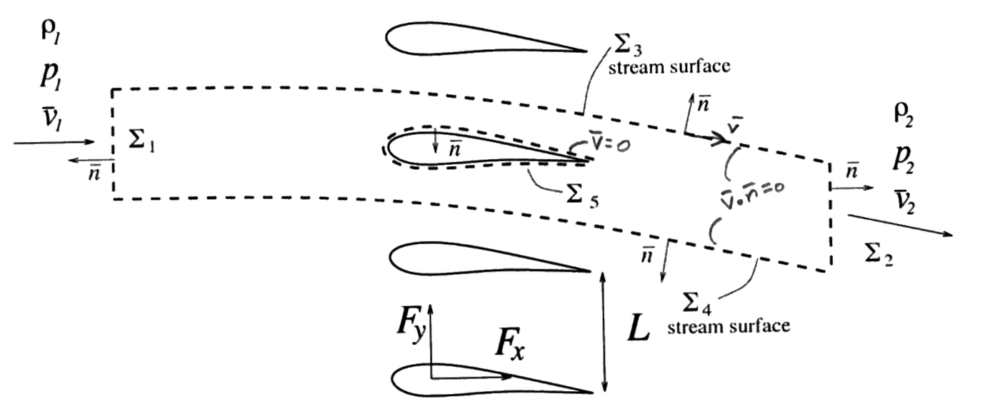
A planar uniform stream of air with pressure $p_1$, density $\rho_1$ and velocity $\bar{v}_1 = v_{1x}\bar{e}_x$ flows past an array of aerofoils with vertical separation $L$, exerting on each one a force (per unit length) given by $\bar{F} = F_x\bar{e}_x + F_y\bar{e}_y$. Assuming that the aerofoils are thermally insulated and neglecting the effect of gravity, write the equations that determine the values of the pressure $p_2$, density $\rho_2$ and velocity $\bar{v}_2 = v_{2x}\bar{e}_x + v_{2y}\bar{e}_y$ for the uniform stream found sufficiently far downstream.

Array of aerofoils a distance L apart in a uniform stream rho1, p1, v1; the official control volume with the upstream section Sigma 1, the downstream section Sigma 2, the stream surfaces Sigma 3 and Sigma 4 and the aerofoil surface Sigma 5; force components Fx, Fy
Swipe sideways to see the whole figure.
Statement figure (CL4.pdf, p. 1, cropped): cascade of aerofoils $L$ apart; the dashed control volume ($\Sigma_1$ to $\Sigma_5$) and the handwritten notes belong to the official sheet
Open the figure full size

Source: CL4.pdf (page 1). Notes.pdf, Chapter 3: integral mass balance Eq. 3.11, integral momentum balance Eq. 3.36, integral total energy balance Eq. 3.46, force on a body Eq. 3.32.

Worked solutionexpand / collapse

Hypotheses, Data and Unknowns

  • Steady planar flow through an infinite array of identical aerofoils (pitch $L$), so the flow is periodic in $y$; uniform far upstream (1) and far downstream (2).
  • Neglect $\bar{g}$; aerofoils thermally insulated; compressible fluid. Viscous stresses and heat conduction negligible in the uniform sections.
  • Perfect gas: $h = e + \frac{p}{\rho} = c_pT = \frac{c_p}{R_g}\frac{p}{\rho} = \frac{\gamma}{\gamma - 1}\frac{p}{\rho}$ (with $p = \rho R_gT$ and $\gamma = c_p/c_v$), as in the class solution.
  • Data: $[p_1,\ \rho_1,\ v_{1x},\ L,\ F_x,\ F_y]$ and, for the perfect gas of the official solution, $\gamma$ (not in the statement). Unknowns: $[p_2,\ \rho_2,\ v_{2x},\ v_{2y}]$: four equations are needed.
SymbolMeaningSI unit
$p_1$, $\rho_1$, $v_{1x}$upstream statePa, kg/m$^3$, m/s
$p_2$, $\rho_2$, $v_{2x}$, $v_{2y}$downstream statePa, kg/m$^3$, m/s
$L$pitch of the arraym
$F_x$, $F_y$force on each aerofoil per unit lengthN/m
$\gamma$specific-heat ratio of the gas (perfect gas, introduced in the solution)1

Frames, Control Volume and Surfaces

  • Frame fixed to the array; $\bar{e}_x$ along the incoming stream, $\bar{e}_y$ along the array. Fixed control volume, $\bar{v}_c = 0$, one period high.
  • Surfaces: $\Sigma_1$ (far upstream, height $L$, $\bar{n} = -\bar{e}_x$), $\Sigma_2$ (far downstream, height $L$, $\bar{n} = +\bar{e}_x$), $\Sigma_{l1}$ and $\Sigma_{l2}$ (upper and lower stream surfaces, $\bar{v}\cdot\bar{n} = 0$), $\Sigma_w$ (aerofoil surface, $\bar{v} = 0$, insulated).
  • Periodicity: $\Sigma_{l2}$ is $\Sigma_{l1}$ shifted by $-L\bar{e}_y$ with opposite normals, so the integrals of any periodic quantity over $\Sigma_{l1}$ and $\Sigma_{l2}$ cancel each other out.
L Σ1 Σ2 Σl1 Σl2 Σw n n n n n v1 = v1xex v2 x y
Swipe sideways to see the whole figure.
Control volume of the solution (as in the class notes): $\Sigma_1$ and $\Sigma_2$ (sections of height $L$), the stream surfaces $\Sigma_{l1}$ and $\Sigma_{l2}$ ($\Sigma_{l2}$ is $\Sigma_{l1}$ shifted by $-L\bar{e}_y$, so their fluxes cancel) and the aerofoil surface $\Sigma_w$. The official figure calls them $\Sigma_1$, $\Sigma_2$, $\Sigma_3$, $\Sigma_4$ and $\Sigma_5$
Open the figure full size

Force on each aerofoil (per unit length), with $\bar{n}$ the outward normal of the control volume:

$$ \boxed{\,\bar{F} = F_x\bar{e}_x + F_y\bar{e}_y = \int_{\Sigma_w}p\,\bar{n}\,d\sigma - \int_{\Sigma_w}\bar{\bar{\tau}}'\cdot\bar{n}\,d\sigma\,} $$

Balances, Surface by Surface

Mass (Notes Eq. 3.11)
$$ \underbrace{\cancel{\frac{d}{dt}\int_{V_c}\rho\,dV}}_{0\ (\text{steady})} + \int_{\Sigma_c}\rho\,(\bar{v} - \underbrace{\cancel{\bar{v}_c}}_{0})\cdot\bar{n}\,d\sigma = 0 $$

Each surface integral, surface by surface (the vertical line drawn under each integral in class):

Surface$\int\rho\,\bar{v}\cdot\bar{n}\,d\sigma$
$\Sigma_1$$\rho_1(-v_{1x})\,L$
$\Sigma_2$$\rho_2\,v_{2x}\,L$
$\Sigma_{l1},\ \Sigma_{l2}$$0$ (stream surfaces)
$\Sigma_w$$0$ (wall)
$$ \boxed{\,\rho_1v_{1x} = \rho_2v_{2x}\,} \tag{1} $$
Linear momentum (Notes Eq. 3.36)
$$ \underbrace{\cancel{\frac{d}{dt}\int_{V_c}\rho\bar{v}\,dV}}_{0\ (\text{steady})} + \int_{\Sigma_c}\rho\bar{v}\,[(\bar{v} - \underbrace{\cancel{\bar{v}_c}}_{0})\cdot\bar{n}]\,d\sigma = -\int_{\Sigma_c}p\,\bar{n}\,d\sigma + \int_{\Sigma_c}\bar{\bar{\tau}}'\cdot\bar{n}\,d\sigma + \underbrace{\cancel{\int_{V_c}\rho\bar{g}\,dV}}_{\text{neglect } \bar{g}} $$

Each surface integral, surface by surface (the vertical line drawn under each integral in class):

Surface$\int\rho\bar{v}\,(\bar{v}\cdot\bar{n})\,d\sigma$$-\int p\,\bar{n}\,d\sigma$$\int\bar{\bar{\tau}}'\cdot\bar{n}\,d\sigma$
$\Sigma_1$$\rho_1v_{1x}\bar{e}_x(-v_{1x})L$$+p_1L\,\bar{e}_x$$0$
$\Sigma_2$$\rho_2(v_{2x}\bar{e}_x + v_{2y}\bar{e}_y)\,v_{2x}L$$-p_2L\,\bar{e}_x$$0$
$\Sigma_{l1} + \Sigma_{l2}$$0$$0$ (cancel each other out)$0$ (cancel each other out)
$\Sigma_w$$0$$-\int_{\Sigma_w}p\,\bar{n}\,d\sigma$$\int_{\Sigma_w}\bar{\bar{\tau}}'\cdot\bar{n}\,d\sigma$

Boxed $\Sigma_w$ terms: $-\bar{F} = -F_x\bar{e}_x - F_y\bar{e}_y$. With (1), $\rho_2v_{2x}L = \rho_1v_{1x}L$ in the $\Sigma_2$ flux.

$$ \boxed{\,F_x = \rho_1v_{1x}L\,(v_{1x} - v_{2x}) + (p_1 - p_2)\,L\,}\ \ \text{(2)}\qquad \boxed{\,F_y = -\rho_1v_{1x}L\,v_{2y}\,}\ \ \text{(3)} $$
Total energy (Notes Eq. 3.46)
$$ \underbrace{\cancel{\frac{d}{dt}\int_{V_c}\rho\left(e + \tfrac{v^2}{2}\right)dV}}_{0} + \int_{\Sigma_c}\rho\left(e + \frac{v^2}{2}\right)(\bar{v}\cdot\bar{n})\,d\sigma = -\int_{\Sigma_c}p\,\bar{v}\cdot\bar{n}\,d\sigma + \int_{\Sigma_c}\bar{v}\cdot(\bar{\bar{\tau}}'\cdot\bar{n})\,d\sigma + \underbrace{\cancel{\int_{V_c}\rho\bar{g}\cdot\bar{v}\,dV}}_{\text{neglect}} - \int_{\Sigma_c}\bar{q}\cdot\bar{n}\,d\sigma + \underbrace{\cancel{\int_{V_c}(Q_c + Q_r)\,dV}}_{0} $$

Each surface integral, surface by surface (the vertical line drawn under each integral in class):

Surface$\int\rho\left(e + \tfrac{v^2}{2}\right)(\bar{v}\cdot\bar{n})\,d\sigma$$-\int p\,\bar{v}\cdot\bar{n}\,d\sigma$$\int\bar{v}\cdot(\bar{\bar{\tau}}'\cdot\bar{n})\,d\sigma$$-\int\bar{q}\cdot\bar{n}\,d\sigma$
$\Sigma_1$$\rho_1\left(e_1 + \tfrac{v_{1x}^2}{2}\right)(-v_{1x})L$$+p_1v_{1x}L$$0$$0$
$\Sigma_2$$\rho_2\left(e_2 + \tfrac{v_{2x}^2 + v_{2y}^2}{2}\right)v_{2x}L$$-p_2v_{2x}L$$0$$0$
$\Sigma_{l1} + \Sigma_{l2}$$0$$0$$0$ (cancel each other out)$0$ (cancel each other out)
$\Sigma_w$$0$$0$ ($\bar{v} = 0$)$0$ ($\bar{v} = 0$)$0$ (insulated)

Moving the pressure work to the left turns $e$ into $h = e + p/\rho$; dividing by $\rho_1v_{1x}L = \rho_2v_{2x}L$ and using $h = \frac{\gamma}{\gamma-1}\frac{p}{\rho}$:

$$ \boxed{\,\frac{\gamma}{\gamma - 1}\left(\frac{p_2}{\rho_2} - \frac{p_1}{\rho_1}\right) + \frac{v_{2x}^2 + v_{2y}^2}{2} - \frac{v_{1x}^2}{2} = 0\,} \tag{4} $$

(1) to (4) are four equations for the four unknowns $p_2$, $\rho_2$, $v_{2x}$, $v_{2y}$, which answers the question.

Interpretation, Limits and Dimensional Check

  • (3): the transverse force on an aerofoil equals minus the $y$ momentum given to the stream; the flow is deflected opposite to the force. (2) splits the streamwise force into a pressure drop and a momentum change.
  • $\bar{F} = 0$: (1) to (4) are satisfied by state 2 = state 1. Incompressible limit ($\rho_2 = \rho_1$): $v_{2x} = v_{1x}$ and $p_1 - p_2 = F_x/L$.
  • Dimensions (SI): $[F_x/L] = \text{Pa} = [\rho_1v_{1x}^2]$; $[\rho_1v_{1x}Lv_{2y}] = \text{N/m}$; $[\gamma p/((\gamma-1)\rho)] = \text{m}^2/\text{s}^2 = [v^2]$.
  • Agreement with the official solution and the class solution: the same four equations (1) to (4).
Extension (beyond the official solution): closed solution

With $m = \rho_1v_{1x}$: $\rho_2 = m/v_{2x}$, $v_{2y} = -F_y/(mL)$ and $p_2 = P - m\,v_{2x}$ with $P = p_1 + mv_{1x} - F_x/L$. Substituting into (4), with $E = \frac{\gamma}{\gamma-1}\frac{p_1}{\rho_1} + \frac{v_{1x}^2}{2}$ and the coefficient $\frac{1}{2} - \frac{\gamma}{\gamma-1} = -\frac{\gamma+1}{2(\gamma-1)}$ of $v_{2x}^2$: $(\gamma + 1)v_{2x}^2 - 2\gamma\frac{P}{m}v_{2x} + 2(\gamma - 1)\left(E - \frac{v_{2y}^2}{2}\right) = 0$. For $\bar{F} = 0$ one root is $v_{2x} = v_{1x}$; the root continuous with it is the physical one. Check: $p_1 = 101325$ Pa, $\rho_1 = 1.2$ kg/m$^3$, $v_{1x} = 100$ m/s, $L = 0.2$ m, $F_x = 30$ N/m, $F_y = -80$ N/m, $\gamma = 1.4$ give $v_{2x} = 100.16$ m/s, $v_{2y} = 3.3333$ m/s, $\rho_2 = 1.19808$ kg/m$^3$, $p_2 = 101155.8$ Pa, residuals of (1) to (4) below $10^{-9}$; the other root gives $p_2 = -6843.3$ Pa $< 0$ and is discarded.

Problem CL5

Turbojet on a Testbench: Exit State

Original statement · CL5.pdf
Moving boundariesMass, momentum, energyHeat and workThrust

Official Problem Statement

The entrance and exit sections of the turboreactor sketched in the figure of CL5.pdf have areas $A_1$ and $A_2$. Besides the outer fixed frame, the machine has mobile parts in its interior that extract an amount of work $W$ per unit time from the fluid stream. The combined effects of chemical reaction in the combustion chamber and heat transfer through the walls give a heat transfer per unit time $Q$ to the fluid stream. The axial force on the turboreactor measured on the testbench is $\bar{F} = -F\,\bar{e}_x$. For given values of $W$, $Q$ and $F$ and assuming that at the entrance and exit sections the flow properties are uniform, obtain the values of the density $\rho_2$, pressure $p_2$ and velocity $v_2$ in terms of their values $p_1$, $\rho_1$ and $v_1$ at the entrance. (Handwritten addition: no gravity.)

A1 A2 v1 p1 ρ1 v2 p2 ρ2 Qr Qc x y n n n Σ1 Σ2 Σ3 Σ4
Swipe sideways to see the whole figure.
Statement figure (redrawn from CL5.pdf, p. 1): entrance $A_1$ ($v_1$, $p_1$, $\rho_1$), exit $A_2$ ($v_2$, $p_2$, $\rho_2$), rotor and heat sources $Q_r$, $Q_c$; the dashed control volume and its surfaces $\Sigma_1$ to $\Sigma_4$ belong to the official figure
Open the figure full size

Source: CL5.pdf (page 1). Notes.pdf, Chapter 3: integral mass balance Eq. 3.10, integral momentum balance Eq. 3.35, integral total energy balance Eq. 3.46, force on a body Eq. 3.32.

Worked solutionexpand / collapse

Hypotheses, Data and Unknowns

  • Compressible flow; neglect gravity; uniform properties at inlet and outlet; steady on average (the rotating parts make the flow periodic inside, but there is no net accumulation).
  • Perfect gas, $h = \frac{\gamma}{\gamma-1}\frac{p}{\rho}$, as in the class solution. Fuel mass flow neglected (not given), so the same mass flow crosses both sections.
  • $\dot{W}$: work per unit time extracted from the fluid by the mobile parts; $\dot{Q}$: heat per unit time transferred to the fluid; $\bar{F} = -F\bar{e}_x$: force on the device measured on the testbench (fluid inside plus ambient air outside, at $p_a$).
  • Data: $[\rho_1,\ p_1,\ \bar{v}_1 = v_1\bar{e}_x,\ A_1,\ A_2,\ F,\ \dot{W},\ \dot{Q}]$ and, introduced in the solution (not in the statement), the ambient pressure $p_a$ and the perfect-gas ratio $\gamma$. Unknowns: $[\rho_2,\ p_2,\ \bar{v}_2 = v_2\bar{e}_x]$.
SymbolMeaningSI unit
$A_1$, $A_2$entrance and exit areasm$^2$
$p_1$, $\rho_1$, $v_1$entrance statePa, kg/m$^3$, m/s
$p_2$, $\rho_2$, $v_2$exit statePa, kg/m$^3$, m/s
$F$thrust measured on the benchN
$\dot{W}$, $\dot{Q}$power extracted and heat addedW
$\dot{m} = \rho_1v_1A_1$mass flowkg/s
$p_a$, $\gamma$ambient pressure and specific-heat ratio (both introduced in the solution)Pa, 1

Frames, Control Volume and Surfaces

  • Frame fixed to the testbench; $\bar{e}_x$ along the engine axis in the flow direction.
  • Surfaces: $\Sigma_1$ (entrance, $\bar{n} = -\bar{e}_x$), $\Sigma_2$ (exit, $\bar{n} = +\bar{e}_x$), $\Sigma_w$ (fixed walls, $\bar{v} = \bar{v}_c = 0$) and $\Sigma_m$ (surface of the mobile parts, moving with them: $\bar{v} = \bar{v}_c \ne 0$). On $\Sigma_w$ and $\Sigma_m$, $(\bar{v} - \bar{v}_c)\cdot\bar{n} = 0$.
  • $\bar{n}$ is the outward normal of the control volume; $\bar{n}_{\text{in}} = -\bar{n}$ points into the fluid.
W Qc QR Σ1 Σ2 Σw Σm n n n v1 v2 F = −F ex ex
Swipe sideways to see the whole figure.
Control volume of the solution (as in the class notes): $\Sigma_1$ (entrance, $\bar{n} = -\bar{e}_x$), $\Sigma_2$ (exit, $\bar{n} = +\bar{e}_x$), the fixed walls $\Sigma_w$ and the surface $\Sigma_m$ of the mobile parts. The official figure calls them $\Sigma_1$, $\Sigma_2$, $\Sigma_3$ and $\Sigma_4$
Open the figure full size

Definitions written on the surfaces, as in class ($Q_R \equiv Q_c + Q_r$ is the volumetric heat release of Notes Eq. 3.46):

$$ \boxed{\,\bar{F} = \int_{\Sigma_m,\Sigma_w}(p - p_a)\,\bar{n}\,d\sigma - \int_{\Sigma_m,\Sigma_w}\bar{\bar{\tau}}'\cdot\bar{n}\,d\sigma = -F\,\bar{e}_x\,} $$
$$ \boxed{\,\dot{Q} = \int_{\Sigma_w,\Sigma_m}\bar{q}\cdot\bar{n}_{\text{in}}\,d\sigma + \int_{V_c}Q_R\,dV\,} $$
$$ \boxed{\,\dot{W} = -\int_{\Sigma_m}p\,\bar{n}_{\text{in}}\cdot\bar{v}\,d\sigma + \int_{\Sigma_m}(\bar{\bar{\tau}}'\cdot\bar{n}_{\text{in}})\cdot\bar{v}\,d\sigma\,} $$

Only $\Sigma_m$ enters $\dot{W}$: $\Sigma_w$ is a fixed surface and does no work. $\dot{W}$ is the power of the gas on the moving solid, so the power done on the gas there is $-\dot{W}$.

Balances, Surface by Surface

Mass (Notes Eq. 3.10)
$$ \underbrace{\cancel{\frac{d}{dt}\int_{V_c}\rho\,dV}}_{0\ (\text{on average})} + \int_{\Sigma_c}\rho\,(\bar{v} - \bar{v}_c)\cdot\bar{n}\,d\sigma = 0 $$

Each surface integral, surface by surface (the vertical line drawn under each integral in class):

Surface$\int\rho\,(\bar{v} - \bar{v}_c)\cdot\bar{n}\,d\sigma$
$\Sigma_1$$-\rho_1v_1A_1$
$\Sigma_2$$+\rho_2v_2A_2$
$\Sigma_m$$0$ ($\bar{v} = \bar{v}_c$)
$\Sigma_w$$0$
$$ \boxed{\,\rho_1v_1A_1 = \rho_2v_2A_2 = \dot{m}\,} \tag{1} $$
Linear momentum (Notes Eq. 3.35)
$$ \underbrace{\cancel{\frac{d}{dt}\int_{V_c}\rho\bar{v}\,dV}}_{0} + \int_{\Sigma_c}\rho\bar{v}\,[(\bar{v} - \bar{v}_c)\cdot\bar{n}]\,d\sigma = -\int_{\Sigma_c}(p - p_a)\,\bar{n}\,d\sigma + \int_{\Sigma_c}\bar{\bar{\tau}}'\cdot\bar{n}\,d\sigma + \underbrace{\cancel{\int_{V_c}\rho\bar{g}\,dV}}_{\text{neglect}} $$

Each surface integral, surface by surface (the vertical line drawn under each integral in class):

Surface$\int\rho\bar{v}\,[(\bar{v} - \bar{v}_c)\cdot\bar{n}]\,d\sigma$$-\int(p - p_a)\,\bar{n}\,d\sigma$$\int\bar{\bar{\tau}}'\cdot\bar{n}\,d\sigma$
$\Sigma_1$$\rho_1v_1\bar{e}_x(-v_1)A_1 = -\dot{m}v_1\bar{e}_x$$(p_1 - p_a)A_1\bar{e}_x$$0$
$\Sigma_2$$\rho_2v_2\bar{e}_x(v_2)A_2 = \dot{m}v_2\bar{e}_x$$-(p_2 - p_a)A_2\bar{e}_x$$0$
$\Sigma_m,\ \Sigma_w$$0$$-\int_{\Sigma_m,\Sigma_w}(p - p_a)\,\bar{n}\,d\sigma$$\int_{\Sigma_m,\Sigma_w}\bar{\bar{\tau}}'\cdot\bar{n}\,d\sigma$

Boxed $\Sigma_m$, $\Sigma_w$ terms: $-\bar{F} = F\bar{e}_x$ (uniform velocity vectors give no viscous stress on $\Sigma_1$, $\Sigma_2$).

$$ \boxed{\,\dot{m}\,(v_2 - v_1) = (p_1 - p_a)A_1 - (p_2 - p_a)A_2 + F\,} \tag{2} $$
Total energy (Notes Eq. 3.46)
$$ \underbrace{\cancel{\frac{d}{dt}\int_{V_c}\rho\left(e + \tfrac{v^2}{2}\right)dV}}_{0} + \int_{\Sigma_c}\rho\left(e + \frac{v^2}{2}\right)[(\bar{v} - \bar{v}_c)\cdot\bar{n}]\,d\sigma = -\int_{\Sigma_c}p\,\bar{v}\cdot\bar{n}\,d\sigma + \int_{\Sigma_c}(\bar{\bar{\tau}}'\cdot\bar{n})\cdot\bar{v}\,d\sigma + \underbrace{\cancel{\int_{V_c}\rho\bar{g}\cdot\bar{v}\,dV}}_{\text{neglect}} - \int_{\Sigma_c}\bar{q}\cdot\bar{n}\,d\sigma + \int_{V_c}Q_R\,dV $$

Each surface integral, surface by surface (the vertical line drawn under each integral in class):

Surface$\int\rho\left(e + \tfrac{v^2}{2}\right)[(\bar{v} - \bar{v}_c)\cdot\bar{n}]\,d\sigma$$-\int p\,\bar{v}\cdot\bar{n}\,d\sigma$$\int(\bar{\bar{\tau}}'\cdot\bar{n})\cdot\bar{v}\,d\sigma$$-\int\bar{q}\cdot\bar{n}\,d\sigma$
$\Sigma_1$$-\dot{m}\left(e_1 + \tfrac{v_1^2}{2}\right)$$+p_1v_1A_1$$0$$0$ ($\nabla T = 0$)
$\Sigma_2$$+\dot{m}\left(e_2 + \tfrac{v_2^2}{2}\right)$$-p_2v_2A_2$$0$$0$ ($\nabla T = 0$)
$\Sigma_m$$0$$-\int_{\Sigma_m}p\,\bar{v}\cdot\bar{n}\,d\sigma$$\int_{\Sigma_m}(\bar{\bar{\tau}}'\cdot\bar{n})\cdot\bar{v}\,d\sigma$$-\int_{\Sigma_m}\bar{q}\cdot\bar{n}\,d\sigma$
$\Sigma_w$$0$$0$ ($\bar{v} = 0$)$0$ ($\bar{v} = 0$)$-\int_{\Sigma_w}\bar{q}\cdot\bar{n}\,d\sigma$

Boxed terms: the pressure and viscous work on $\Sigma_m$ add up to $-\dot{W}$; the conduction through $\Sigma_m$, $\Sigma_w$ plus the volume term $\int_{V_c}Q_R\,dV$ add up to $\dot{Q}$. Moving the pressure work on $\Sigma_1$, $\Sigma_2$ to the left gives $h = e + p/\rho$; with (1) and $h = \frac{\gamma}{\gamma-1}\frac{p}{\rho}$:

$$ \boxed{\,\dot{m}\left[\left(\frac{\gamma}{\gamma - 1}\frac{p_2}{\rho_2} + \frac{v_2^2}{2}\right) - \left(\frac{\gamma}{\gamma - 1}\frac{p_1}{\rho_1} + \frac{v_1^2}{2}\right)\right] = -\dot{W} + \dot{Q}\,} \tag{3} $$

(1), (2) and (3) determine $\rho_2$, $p_2$ and $v_2$.

Interpretation, Limits and Dimensional Check

  • (2) is the thrust balance: thrust = change of momentum flux + pressure imbalance on the sections. For $p_1 = p_2 = p_a$, $F = \dot{m}(v_2 - v_1)$.
  • (3): the stagnation enthalpy of the stream rises by the heat added and falls by the work extracted, per unit mass flow.
  • Dimensions (SI): $[\dot{m}(v_2 - v_1)] = \text{N}$; $[(\dot{Q} - \dot{W})/\dot{m}] = \text{J/kg} = \text{m}^2/\text{s}^2 = [h] = [v^2]$.
  • Numerical illustration (hypothetical data): $A_1 = 0.5$ m$^2$, $A_2 = 0.3$ m$^2$, $v_1 = 150$ m/s, $p_1 = 0.9\times10^5$ Pa, $\rho_1 = 1.1$ kg/m$^3$ ($M_1 = 0.443$), $p_a = 10^5$ Pa, $F = 30$ kN, $\dot{W} = 2$ MW, $\dot{Q} = 30$ MW, $\gamma = 1.4$: $\dot{m} = 82.5$ kg/s and the two roots of the extension below, $v_2 = 355.515$ m/s, $p_2 = 126817$ Pa, $\rho_2 = 0.77353$ kg/m$^3$ ($M_2 = 0.742$), and $v_2 = 597.263$ m/s, $p_2 = 60336$ Pa, $\rho_2 = 0.46043$ kg/m$^3$ ($M_2 = 1.39$); residuals of (1) to (3) below $10^{-6}$ in SI units.
  • Agreement with the official and class solutions: the same equations (1), (2), (3) (CL5.pdf writes (2) as $F = \rho_1v_1A_1(v_2 - v_1) - (p_1 - p_a)A_1 + (p_2 - p_a)A_2$).
Extension (beyond the official solution): explicit solution

With $K = p_aA_2 + F + (p_1 - p_a)A_1 + \dot{m}v_1$, (2) gives $p_2A_2 = K - \dot{m}v_2$ and, with (1), $p_2/\rho_2 = (K - \dot{m}v_2)v_2/\dot{m}$. Substituting into (3) and using $\frac{1}{2} - \frac{\gamma}{\gamma-1} = -\frac{\gamma+1}{2(\gamma-1)}$: $(\gamma + 1)v_2^2 - 2\gamma\frac{K}{\dot{m}}v_2 + 2(\gamma - 1)H_0 = 0$, with $H_0 = \frac{\gamma}{\gamma-1}\frac{p_1}{\rho_1} + \frac{v_1^2}{2} + \frac{\dot{Q} - \dot{W}}{\dot{m}}$. The two roots are a subsonic and a supersonic exit state; for a subsonic entrance with heat addition the physical one is the subsonic (smaller) root, since reaching the other would require passing through sonic conditions inside the engine, which this overall balance cannot describe. For $F = 0$, $\dot{Q} = \dot{W} = 0$ and $A_1 = A_2$ one root is $v_2 = v_1$ and the product of the roots is $2(\gamma - 1)H_0/(\gamma + 1)$, the Prandtl relation of a normal shock.

Problem CL6

Elbow Discharging a Vertical Jet: Velocity, Force and Heat

Original statement · CL6.pdf
ElbowLinear momentumEnergyHeat through the walls

Official Problem Statement

A liquid of density $\rho$ and specific heat $c$ flows through the elbow-shaped pipe shown in CL6.pdf, discharging to the atmosphere as a vertical jet through an outlet section of surface area $A_o$, different from the value $A_i$ at the inlet. Gravity is assumed to have a negligible effect on the fluid motion. Besides, uniform flow properties are assumed at the inlet and outlet sections, where readings from a thermometer give different values $T_i$ and $T_o$ for the temperature. The velocity at the outlet section is measured to be $v_o$ and a manometer is used to determine the value $p_i$ for the pressure at the inlet section. In terms of all of these quantities, determine:

  • The value of the velocity at the inlet $v_i$.
  • The two components of the force $(F_x, F_z)$ exerted on the pipe.
  • The amount of heat $Q$ transferred per unit time to the liquid by heat conduction through the pipe walls.
vi pi Ti Ai Fz Fx Q pa pa pa vo To Ao
Swipe sideways to see the whole figure.
Statement figure (redrawn from CL6.pdf, p. 1): inlet section $A_i$ with $v_i$, $p_i$, $T_i$; outlet $A_o$ discharging a vertical jet $v_o$, $T_o$ into $p_a$; force components $F_x$, $F_z$ on the pipe and heat $Q$ through its walls
Open the figure full size

Source: CL6.pdf (page 1), also solved in class (class notes, CL6). Notes.pdf, Chapter 3: integral mass balance Eq. 3.11, integral momentum balance Eq. 3.36, integral total energy balance Eq. 3.46.

Worked solutionexpand / collapse

Hypotheses, Data and Unknowns

  • Steady, incompressible liquid, $e = cT$; neglect $\bar{g}$; uniform properties at inlet and outlet (no viscous stresses or conduction across them).
  • Free jet: $p = p_a$ over the outlet section. The outer face of the pipe is in contact with the ambient air at $p_a$, so the force on the pipe is computed with gauge pressure $p - p_a$.
  • Geometry (figure): the liquid enters horizontally along $+\bar{e}_x$ and leaves as a vertical jet along $-\bar{e}_z$ ($\bar{e}_z$ upwards).
  • Data: $[\rho,\ c,\ A_i,\ A_o,\ v_o,\ p_i,\ p_a,\ T_i,\ T_o]$. Unknowns: $[v_i,\ F_x,\ F_z,\ \dot{Q}]$.
SymbolMeaningSI unit
$A_i$, $A_o$inlet and outlet areasm$^2$
$v_i$, $v_o$inlet and outlet velocitiesm/s
$p_i$, $p_a$inlet and ambient pressuresPa
$T_i$, $T_o$inlet and outlet temperaturesK
$c$specific heat of the liquidJ/(kg$\cdot$K)
$\dot{Q}$heat per unit time into the liquidW
$\rho$liquid densitykg/m$^3$

Frames, Control Volume and Surfaces

  • Frame fixed to the pipe, $\bar{e}_x$ horizontal (inlet flow direction), $\bar{e}_z$ vertical upwards. Fixed control volume: the liquid inside the pipe, $\bar{v}_c = 0$.
  • Surfaces: $\Sigma_i$ (inlet, $\bar{n} = -\bar{e}_x$, $\bar{v} = v_i\bar{e}_x$), $\Sigma_o$ (outlet, $\bar{n} = -\bar{e}_z$, $\bar{v} = -v_o\bar{e}_z$), $\Sigma_w$ (pipe wall, $\bar{v} = 0$).
Σi Σw Σo n n n vi vo x z
Swipe sideways to see the whole figure.
Control volume of the solution (as in the class notes): the liquid inside the pipe, with $\Sigma_i$ (inlet, $\bar{n} = -\bar{e}_x$), $\Sigma_o$ (outlet, $\bar{n} = -\bar{e}_z$) and the wall $\Sigma_w$, where the force and the heat are collected
Open the figure full size

Force of the liquid and the ambient air on the pipe, and heat through the walls, written on $\Sigma_w$:

$$ \boxed{\,\bar{F} = F_x\bar{e}_x + F_z\bar{e}_z = \int_{\Sigma_w}(p - p_a)\,\bar{n}\,d\sigma - \int_{\Sigma_w}\bar{\bar{\tau}}'\cdot\bar{n}\,d\sigma\,} $$
$$ \boxed{\,\dot{Q} = -\int_{\Sigma_w}\bar{q}\cdot\bar{n}\,d\sigma\,} $$

Balances, Surface by Surface

Mass (Notes Eq. 3.11)
$$ \underbrace{\cancel{\frac{d}{dt}\int_{V_c}\rho\,dV}}_{0\ (\text{steady})} + \int_{\Sigma_c}\rho\,(\bar{v} - \underbrace{\cancel{\bar{v}_c}}_{0})\cdot\bar{n}\,d\sigma = 0 $$

Each surface integral, surface by surface (the vertical line drawn under each integral in class):

Surface$\int\rho\,\bar{v}\cdot\bar{n}\,d\sigma$
$\Sigma_i$$\rho\,v_i\bar{e}_x\cdot(-\bar{e}_x)A_i = -\rho v_iA_i$
$\Sigma_o$$\rho\,(-v_o\bar{e}_z)\cdot(-\bar{e}_z)A_o = +\rho v_oA_o$
$\Sigma_w$$0$
$$ \boxed{\,v_i = \frac{A_o}{A_i}\,v_o\,},\qquad \dot{m} = \rho v_iA_i = \rho v_oA_o \tag{1} $$
Linear momentum (Notes Eq. 3.36)
$$ \underbrace{\cancel{\frac{d}{dt}\int_{V_c}\rho\bar{v}\,dV}}_{0\ (\text{steady})} + \int_{\Sigma_c}\rho\bar{v}\,[(\bar{v} - \underbrace{\cancel{\bar{v}_c}}_{0})\cdot\bar{n}]\,d\sigma = -\int_{\Sigma_c}(p - p_a)\,\bar{n}\,d\sigma + \int_{\Sigma_c}\bar{\bar{\tau}}'\cdot\bar{n}\,d\sigma + \underbrace{\cancel{\int_{V_c}\rho\bar{g}\,dV}}_{\text{neglect } \bar{g}} $$

Each surface integral, surface by surface (the vertical line drawn under each integral in class):

Surface$\int\rho\bar{v}\,(\bar{v}\cdot\bar{n})\,d\sigma$$-\int(p - p_a)\,\bar{n}\,d\sigma$$\int\bar{\bar{\tau}}'\cdot\bar{n}\,d\sigma$
$\Sigma_i$$\rho v_i\bar{e}_x\,(-v_i)A_i = -\rho v_i^2A_i\,\bar{e}_x$$-(p_i - p_a)(-\bar{e}_x)A_i = (p_i - p_a)A_i\,\bar{e}_x$$0$
$\Sigma_o$$\rho(-v_o\bar{e}_z)\,(v_o)A_o = -\rho v_o^2A_o\,\bar{e}_z$$0$ (free jet)$0$
$\Sigma_w$$0$$-\int_{\Sigma_w}(p - p_a)\,\bar{n}\,d\sigma$$\int_{\Sigma_w}\bar{\bar{\tau}}'\cdot\bar{n}\,d\sigma$

Boxed $\Sigma_w$ terms: $-\bar{F}$.

$$ -\rho v_i^2A_i\,\bar{e}_x - \rho v_o^2A_o\,\bar{e}_z = (p_i - p_a)A_i\,\bar{e}_x - \bar{F} \;\Longrightarrow\; \boxed{\,F_x = \left[\rho v_i^2 + (p_i - p_a)\right]A_i,\qquad F_z = \rho v_o^2A_o\,} \tag{2} $$
Total energy (Notes Eq. 3.46; $Q_R \equiv Q_c + Q_r$ is the volumetric heat release)
$$ \underbrace{\cancel{\frac{d}{dt}\int_{V_c}\rho\left(e + \tfrac{v^2}{2}\right)dV}}_{0\ (\text{steady})} + \int_{\Sigma_c}\rho\left(e + \frac{v^2}{2}\right)[(\bar{v} - \underbrace{\cancel{\bar{v}_c}}_{0})\cdot\bar{n}]\,d\sigma = -\int_{\Sigma_c}p\,\bar{v}\cdot\bar{n}\,d\sigma + \int_{\Sigma_c}\bar{v}\cdot(\bar{\bar{\tau}}'\cdot\bar{n})\,d\sigma + \underbrace{\cancel{\int_{V_c}\rho\bar{g}\cdot\bar{v}\,dV}}_{\text{neglect } \bar{g}} - \int_{\Sigma_c}\bar{q}\cdot\bar{n}\,d\sigma + \underbrace{\cancel{\int_{V_c}Q_R\,dV}}_{0} $$

Each surface integral, surface by surface (the vertical line drawn under each integral in class):

Surface$\int\rho\left(e + \tfrac{v^2}{2}\right)(\bar{v}\cdot\bar{n})\,d\sigma$$-\int p\,\bar{v}\cdot\bar{n}\,d\sigma$$\int\bar{v}\cdot(\bar{\bar{\tau}}'\cdot\bar{n})\,d\sigma$$-\int\bar{q}\cdot\bar{n}\,d\sigma$
$\Sigma_i$$-\dot{m}\left(cT_i + \tfrac{v_i^2}{2}\right)$$+p_iv_iA_i$$0$$0$ (uniform $T$)
$\Sigma_o$$+\dot{m}\left(cT_o + \tfrac{v_o^2}{2}\right)$$-p_av_oA_o$$0$$0$ (uniform $T$)
$\Sigma_w$$0$$0$ ($\bar{v} = 0$)$0$ ($\bar{v} = 0$)$-\int_{\Sigma_w}\bar{q}\cdot\bar{n}\,d\sigma$

Boxed $\Sigma_w$ term: $\dot{Q}$. Using (1), $p_iv_iA_i - p_av_oA_o = (p_i - p_a)\,v_oA_o$.

$$ \dot{m}\left[c(T_o - T_i) + \frac{v_o^2 - v_i^2}{2}\right] = (p_i - p_a)\,v_oA_o + \dot{Q} \;\Longrightarrow\; \boxed{\,\dot{Q} = \rho v_oA_o\left[c(T_o - T_i) + \frac{v_o^2 - v_i^2}{2}\right] + (p_a - p_i)\,v_oA_o\,} \tag{3} $$

Interpretation, Limits and Dimensional Check

  • $F_x > 0$: the pipe is pushed along the incoming flow by the momentum flux and the gauge pressure at the inlet. $F_z > 0$: the jet leaves downwards, so the pipe is pushed upwards.
  • (3) splits the heat into the rise of internal energy, the change of kinetic energy and the flow work. If no heat were exchanged and there were no losses, (3) with $\dot{Q} = 0$ and $T_o = T_i$ would reduce to Bernoulli's equation $p_i + \tfrac{1}{2}\rho v_i^2 = p_a + \tfrac{1}{2}\rho v_o^2$.
  • Dimensions (SI): $[\rho v_i^2A_i] = [(p_i - p_a)A_i] = \text{N}$; $[\rho v_oA_o\,c\,\Delta T] = (\text{kg/s})(\text{J/(kg K)})\,\text{K} = \text{W}$; $[(p_a - p_i)v_oA_o] = \text{Pa}\cdot\text{m}^3/\text{s} = \text{W}$.
  • Numerical illustration (hypothetical data): water, $c = 4186$ J/(kg K), $A_i = 0.01$ m$^2$, $A_o = 0.004$ m$^2$, $v_o = 6$ m/s, $p_i = 1.6\times10^5$ Pa, $p_a = 101325$ Pa, $T_o - T_i = 0.5$ K give $v_i = 2.4$ m/s, $F_x = 644.35$ N, $F_z = 144$ N and $\dot{Q} = 49187$ W.
  • Agreement with the official and class solutions: (1), (2) and (3) are the results of CL6.pdf (which labels the vertical axis $y$: $F_y = \rho v_o^2A_o$) and of the class notes.
Problem CL7

Industrial Dryer: Velocities, Force, Power and Torque

Original statement · CL7.pdf
AxisymmetricAngular momentumEnergyIdeal gas

Official Problem Statement

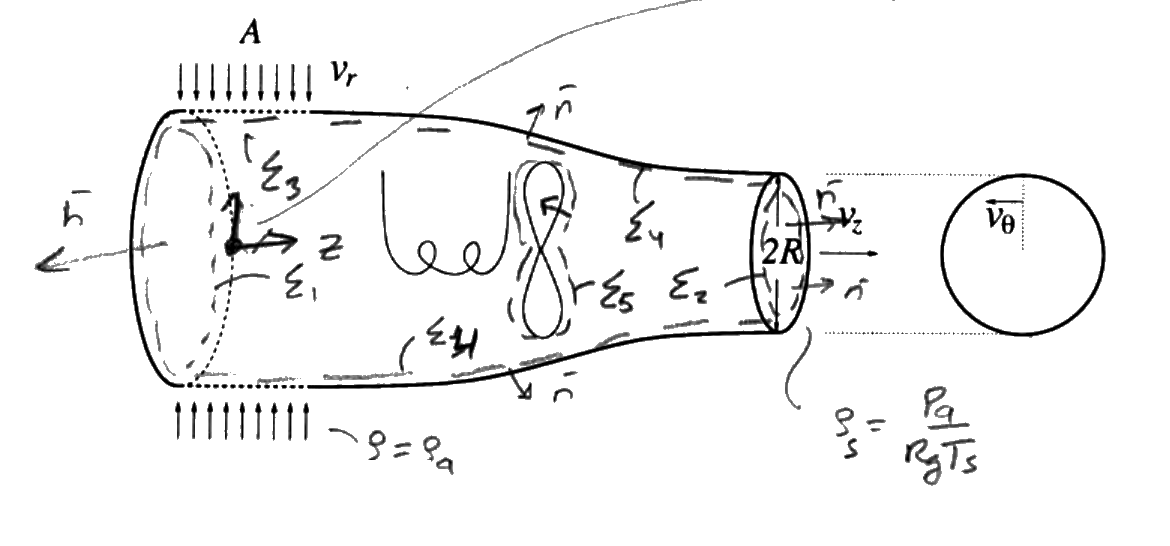
The axisymmetric industrial dryer of the figure in CL7.pdf is designed to provide a steady hot jet of radius $R$, mass flux $G$, and temperature $T_s$. Air enters the dryer from the ambient, at temperature and pressure $T_a$ and $p_a$, through a radial inlet of surface $A$. Inside the dryer there exists an electric resistance that releases an amount of heat $Q$ per unit time, as well as a fan of power $W$ (work per unit time). Because of the presence of the fan, the air velocity at the exit has both azimuthal and axial components, $v_\theta$ and $v_z$, such that $v_\theta/v_z = \tan(\beta)$. In the analysis, assume that the fan and the inner walls of the dryer are thermally insulated, that the air behaves as an ideal gas with constant $R_g$ and specific heat at constant pressure $c_p$, that gravity has a negligible effect on the fluid motion, and that the flow properties are uniform at the inlet and outlet sections. For given values of $G$, $T_s$, $T_a$, $p_a$, $A$, $R$, $R_g$, $c_p$ and $\tan(\beta)$, determine:

  • The velocity at the entrance section $v_r$ as well as the two velocity components at the exit $v_\theta$ and $v_z$.
  • The force acting on the dryer, indicating clearly its magnitude and direction.
  • The total power required to run the dryer $Q + W$.
  • The torque acting on the dryer.
Axisymmetric dryer: radial inlet of area A with velocity vr at rho a, resistance and fan inside, exit of radius R with axial and azimuthal velocities vz, v theta
Swipe sideways to see the whole figure.
Statement figure (CL7.pdf, p. 1, cropped): radial inlet $A$ ($v_r$, $\rho_a$), resistance and fan, exit of diameter $2R$ with $v_z$ and $v_\theta$; the surface names and notes are handwritten on the official sheet
Open the figure full size

Source: CL7.pdf (page 1). Notes.pdf, Chapter 3: integral mass balance Eq. 3.11, integral momentum balance Eq. 3.35, integral angular momentum balance Eq. 3.38, integral total energy balance Eq. 3.46.

Worked solutionexpand / collapse

Hypotheses, Data and Unknowns

  • Steady (on average) axisymmetric flow; ideal gas $p = \rho R_gT$, so $h = e + p/\rho = c_pT$; neglect $\bar{g}$; uniform properties at inlet and outlet.
  • Inlet: air taken from the ambient, with $p = p_a$, $T = T_a$, $\rho_a = p_a/(R_gT_a)$ and radial velocity $v_r$ pointing inwards (as in the official solution). Exit: free jet, $p = p_a$, $T = T_s$, $\rho_s = p_a/(R_gT_s)$, velocity $v_z\bar{e}_z + v_\theta\bar{e}_\theta$ uniform over the disc of radius $R$.
  • $G$ is the mass flow rate of the jet (kg/s), as used in the official solution ($G = \rho_av_rA$). Fan and inner walls insulated; the resistance releases $\dot{Q}$; the fan delivers the power $\dot{W}$ to the air.
  • Data: $[G,\ T_s,\ T_a,\ p_a,\ A,\ R,\ R_g,\ c_p,\ \tan\beta]$. Unknowns: $[v_r,\ v_z,\ v_\theta,\ \bar{F},\ \dot{Q} + \dot{W},\ \bar{M}]$.
SymbolMeaningSI unit
$G$mass flow ratekg/s
$A$, $R$inlet area, jet radiusm$^2$, m
$v_r$, $v_z$, $v_\theta$inlet and exit velocitiesm/s
$R_g$, $c_p$gas constant, specific heatJ/(kg$\cdot$K)
$\bar{F}$, $\bar{M}$force and torque on the dryerN, N$\cdot$m
$T_s$, $T_a$, $p_a$exit and ambient temperatures, ambient pressureK, K, Pa
$\tan\beta = v_\theta/v_z$swirl ratio at the exit1

Frames, Control Volume and Surfaces

  • Frame fixed to the dryer; cylindrical basis $(\bar{e}_r, \bar{e}_\theta, \bar{e}_z)$ with $\bar{e}_z$ along the axis in the jet direction; origin on the axis. By axisymmetry the integrals of the unit vectors over a full turn vanish: with two fixed unit vectors $\bar{e}_x$, $\bar{e}_y$ normal to the axis ($\bar{e}_x\wedge\bar{e}_y = \bar{e}_z$), $\bar{e}_r = \cos\theta\,\bar{e}_x + \sin\theta\,\bar{e}_y$ and $\bar{e}_\theta = -\sin\theta\,\bar{e}_x + \cos\theta\,\bar{e}_y$, so $\int_0^{2\pi}\bar{e}_r\,d\theta = [\sin\theta]_0^{2\pi}\,\bar{e}_x + [-\cos\theta]_0^{2\pi}\,\bar{e}_y = \bar{0}$ and $\int_0^{2\pi}\bar{e}_\theta\,d\theta = [\cos\theta]_0^{2\pi}\,\bar{e}_x + [\sin\theta]_0^{2\pi}\,\bar{e}_y = \bar{0}$.
  • Surfaces: $\Sigma_1$ (radial inlet, area $A$, $\bar{n} = \bar{e}_r$, $\bar{v} = -v_r\bar{e}_r$), $\Sigma_2$ (exit disc, $\bar{n} = \bar{e}_z$), $\Sigma_w$ (fixed casing and resistance, $\bar{v} = 0$) and $\Sigma_m$ (fan blades, $\bar{v} = \bar{v}_c$).
vr vz Σ1 Σ1 Σ2 Σw Σm n n Q ez er
Swipe sideways to see the whole figure.
Control volume of the solution (schematic axial section): $\Sigma_1$ (radial inlet of area $A$, $\bar{n} = \bar{e}_r$, $\bar{v} = -v_r\bar{e}_r$), $\Sigma_2$ (exit disc of radius $R$, $\bar{n} = \bar{e}_z$), $\Sigma_w$ (fixed casing and resistance) and $\Sigma_m$ (fan blades, dashed around them); the heat $Q$ is released by the resistance
Open the figure full size

Force and torque of the air (inside, and ambient outside) on the dryer, and the heat and work exchanged:

$$ \boxed{\,\bar{F} = \int_{\Sigma_w,\Sigma_m}\left[(p - p_a)\,\bar{n} - \bar{\bar{\tau}}'\cdot\bar{n}\right]d\sigma\,} $$
$$ \boxed{\,\bar{M} = \int_{\Sigma_w,\Sigma_m}\bar{x}\wedge\left[(p - p_a)\,\bar{n} - \bar{\bar{\tau}}'\cdot\bar{n}\right]d\sigma\,} $$

Balances, Surface by Surface

Mass (Notes Eq. 3.11)
$$ \underbrace{\cancel{\frac{d}{dt}\int_{V_c}\rho\,dV}}_{0\ (\text{steady})} + \int_{\Sigma_c}\rho\,(\bar{v} - \bar{v}_c)\cdot\bar{n}\,d\sigma = 0 $$

Each surface integral, surface by surface (the vertical line drawn under each integral in class):

Surface$\int\rho\,(\bar{v} - \bar{v}_c)\cdot\bar{n}\,d\sigma$
$\Sigma_1$$\rho_a(-v_r)A = -\rho_av_rA$
$\Sigma_2$$\rho_sv_z\pi R^2$
$\Sigma_w,\ \Sigma_m$$0$
$$ G = \frac{p_a}{R_gT_a}\,v_rA = \frac{p_a}{R_gT_s}\,v_z\pi R^2 \;\Longrightarrow\; \boxed{\,v_r = \frac{GR_gT_a}{p_aA},\qquad v_z = \frac{GR_gT_s}{p_a\pi R^2},\qquad v_\theta = v_z\tan\beta\,} \tag{1} $$
Linear momentum (Notes Eq. 3.35)
$$ \underbrace{\cancel{\frac{d}{dt}\int_{V_c}\rho\bar{v}\,dV}}_{0\ (\text{steady})} + \int_{\Sigma_c}\rho\bar{v}\,[(\bar{v} - \bar{v}_c)\cdot\bar{n}]\,d\sigma = -\int_{\Sigma_c}(p - p_a)\,\bar{n}\,d\sigma + \int_{\Sigma_c}\bar{\bar{\tau}}'\cdot\bar{n}\,d\sigma + \underbrace{\cancel{\int_{V_c}\rho\bar{g}\,dV}}_{\text{neglect } \bar{g}} $$

Each surface integral, surface by surface (the vertical line drawn under each integral in class):

Surface$\int\rho\bar{v}\,[(\bar{v} - \bar{v}_c)\cdot\bar{n}]\,d\sigma$$-\int(p - p_a)\,\bar{n}\,d\sigma$$\int\bar{\bar{\tau}}'\cdot\bar{n}\,d\sigma$
$\Sigma_1$$\rho_av_r^2\int_{\Sigma_1}\bar{e}_r\,d\sigma = 0$ (axisymmetric)$0$ ($p = p_a$)$0$
$\Sigma_2$$\rho_sv_z\int_{\Sigma_2}(v_z\bar{e}_z + v_\theta\bar{e}_\theta)\,d\sigma = \rho_sv_z^2\pi R^2\,\bar{e}_z$$0$ (free jet)$0$
$\Sigma_w,\ \Sigma_m$$0$$-\int(p - p_a)\,\bar{n}\,d\sigma$$\int\bar{\bar{\tau}}'\cdot\bar{n}\,d\sigma$

Boxed terms: $-\bar{F}$. On $\Sigma_2$, $\int_{\Sigma_2}\bar{e}_\theta\,d\sigma = 0$, so the swirl gives no force.

$$ \rho_sv_z^2\pi R^2\,\bar{e}_z = -\bar{F} \;\Longrightarrow\; \boxed{\,\bar{F} = -\frac{p_a}{R_gT_s}\,v_z^2\,\pi R^2\,\bar{e}_z = -G\,v_z\,\bar{e}_z\,} \tag{2} $$
Total energy (Notes Eq. 3.46; $Q_R \equiv Q_c + Q_r$ is the volumetric heat release)
$$ \underbrace{\cancel{\frac{d}{dt}\int_{V_c}\rho\left(e + \tfrac{v^2}{2}\right)dV}}_{0\ (\text{steady})} + \int_{\Sigma_c}\rho\left(e + \frac{v^2}{2}\right)[(\bar{v} - \bar{v}_c)\cdot\bar{n}]\,d\sigma = -\int_{\Sigma_c}p\,\bar{v}\cdot\bar{n}\,d\sigma + \int_{\Sigma_c}\bar{v}\cdot(\bar{\bar{\tau}}'\cdot\bar{n})\,d\sigma + \underbrace{\cancel{\int_{V_c}\rho\bar{g}\cdot\bar{v}\,dV}}_{\text{neglect } \bar{g}} - \int_{\Sigma_c}\bar{q}\cdot\bar{n}\,d\sigma + \underbrace{\cancel{\int_{V_c}Q_R\,dV}}_{0} $$

Each surface integral, surface by surface (the vertical line drawn under each integral in class):

Surface$\int\rho\left(e + \tfrac{v^2}{2}\right)(\bar{v}\cdot\bar{n})\,d\sigma$$-\int p\,\bar{v}\cdot\bar{n}\,d\sigma$$\int\bar{v}\cdot(\bar{\bar{\tau}}'\cdot\bar{n})\,d\sigma$$-\int\bar{q}\cdot\bar{n}\,d\sigma$
$\Sigma_1$$-G\left(e_a + \tfrac{v_r^2}{2}\right)$$+p_av_rA$$0$$0$
$\Sigma_2$$+G\left(e_s + \tfrac{v_\theta^2 + v_z^2}{2}\right)$$-p_av_z\pi R^2$$0$$0$
$\Sigma_m$$0$$-\int_{\Sigma_m}p\,\bar{v}\cdot\bar{n}\,d\sigma$$\int_{\Sigma_m}\bar{v}\cdot(\bar{\bar{\tau}}'\cdot\bar{n})\,d\sigma$$0$ (insulated)
$\Sigma_w$$0$$0$$0$$-\int_{\Sigma_w}\bar{q}\cdot\bar{n}\,d\sigma$

Boxed terms: the work on $\Sigma_m$ is the fan power $\dot{W}$; the heat through $\Sigma_w$ (only the resistance, the walls are insulated) is $\dot{Q}$. With $p_av_rA = G\,p_a/\rho_a$ and $p_av_z\pi R^2 = G\,p_a/\rho_s$, $e + p/\rho = c_pT$:

$$ \boxed{\,\dot{Q} + \dot{W} = G\left[\left(c_pT_s + \frac{v_\theta^2 + v_z^2}{2}\right) - \left(c_pT_a + \frac{v_r^2}{2}\right)\right]\,} \tag{3} $$
Angular momentum about the origin, z component (Notes Eq. 3.38)
$$ \underbrace{\cancel{\frac{d}{dt}\int_{V_c}\rho\,\bar{x}\wedge\bar{v}\,dV}}_{0} + \int_{\Sigma_c}\rho\,(\bar{x}\wedge\bar{v})[(\bar{v} - \bar{v}_c)\cdot\bar{n}]\,d\sigma = -\int_{\Sigma_c}\bar{x}\wedge(p - p_a)\bar{n}\,d\sigma + \int_{\Sigma_c}\bar{x}\wedge(\bar{\bar{\tau}}'\cdot\bar{n})\,d\sigma $$

Each surface integral, surface by surface (the vertical line drawn under each integral in class):

Surface$\int\rho\,(\bar{x}\wedge\bar{v})_z\,[(\bar{v} - \bar{v}_c)\cdot\bar{n}]\,d\sigma$$\text{pressure and viscous moments}$
$\Sigma_1$$0$ ($\bar{x}\wedge(-v_r\bar{e}_r) = -zv_r\,\bar{e}_\theta$, no $z$ component)$0$
$\Sigma_2$$\int_0^R\rho_sv_z\,(rv_\theta)\,2\pi r\,dr = \rho_sv_zv_\theta\,\frac{2\pi R^3}{3}$$0$
$\Sigma_w,\ \Sigma_m$$0$$-\bar{M}\cdot\bar{e}_z$

On $\Sigma_2$, $\bar{x} = r\bar{e}_r + z_2\bar{e}_z$ and $\bar{x}\wedge(v_z\bar{e}_z + v_\theta\bar{e}_\theta) = -rv_z\bar{e}_\theta + rv_\theta\bar{e}_z - z_2v_\theta\bar{e}_r$; only $rv_\theta\bar{e}_z$ survives the integral. The antiderivative of $r^2$ is $r^3/3$, and Barrow's rule between $0$ and $R$ gives $R^3/3$.

$$ \boxed{\,\bar{M} = -\rho_sv_zv_\theta\,\frac{2\pi R^3}{3}\,\bar{e}_z = -\frac{2}{3}\,R\,G\,v_\theta\,\bar{e}_z\,} \tag{4} $$
Erratum in the official solution (slip in the boxed result)

CL7.pdf writes the momentum balance as $\frac{p_a}{R_gT_s}v_z^2\pi R^2\bar{e}_z = -\bar{F}$ but boxes $\bar{F} = -\frac{p_a}{R_gT_s}v_z^2\bar{e}_z$, without the area $\pi R^2$. That expression has units of pressure, not force; the correct result is (2).

Interpretation, Limits and Dimensional Check

  • The radial inflow gives no net momentum (axisymmetry), so the force is the reaction to the jet: magnitude $Gv_z$, direction $-\bar{e}_z$ (opposite to the jet).
  • The swirl gives no force but gives a torque: the fan sets the air rotating, and the air reacts on the dryer with $\bar{M}$ opposite to the swirl. For $\beta = 0$, $v_\theta = 0$ and $\bar{M} = 0$.
  • (3): the electric and mechanical power go into heating the air from $T_a$ to $T_s$ and into its kinetic energy.
  • Dimensions (SI): $[Gv_z] = \text{N}$; $[RGv_\theta] = \text{m}\cdot(\text{kg/s})(\text{m/s}) = \text{N}\cdot\text{m}$; $[Gc_pT] = \text{W}$.
  • Numerical illustration (hypothetical data): $G = 0.5$ kg/s, $T_s = 350$ K, $T_a = 293$ K, $p_a = 101325$ Pa, $A = 0.05$ m$^2$, $R = 0.05$ m, $R_g = 287$ J/(kg K), $c_p = 1005$ J/(kg K), $\tan\beta = 0.5$ give $v_r = 8.2991$ m/s, $v_z = 63.112$ m/s, $v_\theta = 31.556$ m/s, $|\bar{F}| = 31.556$ N, $\dot{Q} + \dot{W} = 29870$ W and $|\bar{M}| = 0.52594$ N$\cdot$m (a midpoint quadrature of the torque integral gives the same value).
Problem CL8

Jet Impinging on a Wall with an Orifice

Original statement · CL8.pdf
Free jetsBernoulliMassForce on a wall

Official Problem Statement

A circular water jet of diameter $D_j$ and velocity $V_j$ impinges perpendicularly to a wall, where there exists an orifice centered at the jet axis, as shown in the figure of CL8.pdf, so that part of the water flows through the orifice and part is deflected to flow next to the wall. Assuming that the flow velocity is sufficiently large for the effects of viscosity and gravity to be negligible:

  • Determine the values of the velocities $V_s$ and $V_r$ for the secondary jet that emerges from the orifice and for the radial wall jet.
  • Obtain the thickness $h(r)$ of the radial wall jet.
  • Compute the force that the jet exerts on the wall as a function of $\rho$, $V_j$, $D_j$ and $D_s$.
Vj Dj Vr h(r) Ds Vs pa pa ex
Swipe sideways to see the whole figure.
Statement figure (redrawn from CL8.pdf, p. 1, axial section): incoming jet $D_j$, $V_j$; orifice of diameter $D_s$ with the secondary jet $V_s$; radial wall jet $V_r$ of thickness $h(r)$; ambient pressure $p_a$ on both sides of the wall
Open the figure full size

Source: CL8.pdf (page 1). Notes.pdf: Bernoulli's equation Eq. 4.17 (Chapter 4), integral mass balance Eq. 3.11, integral momentum balance Eq. 3.36.

Worked solutionexpand / collapse

Hypotheses, Data and Unknowns

  • Steady, incompressible, frictionless (viscosity negligible); neglect $\bar{g}$ (buoyancy-free).
  • Free jets surrounded by the ambient air at $p_a$. In each jet away from the wall the streamlines are straight and parallel (aligned), so the pressure does not vary across them: $p = p_a$ inside the incoming jet, the secondary jet and the wall jet (official solution).
  • Data: $[\rho,\ V_j,\ D_j,\ D_s]$. Unknowns: $[V_s,\ V_r,\ h(r),\ \bar{F}_w]$.
SymbolMeaningSI unit
$V_j$, $D_j$velocity and diameter of the jetm/s, m
$V_s$, $D_s$secondary jet velocity, orifice diameterm/s, m
$V_r$, $h(r)$wall-jet velocity and thicknessm/s, m
$\bar{F}_w$force of the jet on the wallN

Frames, Control Volume and Surfaces

  • Frame fixed to the wall; $\bar{e}_x$ along the jet axis (towards the wall); cylindrical coordinate $r$ on the wall, with two fixed unit vectors $\bar{e}_y$, $\bar{e}_z$ normal to $\bar{e}_x$, $\bar{e}_r = \cos\theta\,\bar{e}_y + \sin\theta\,\bar{e}_z$ and $\int_0^{2\pi}\bar{e}_r\,d\theta = [\sin\theta]_0^{2\pi}\,\bar{e}_y + [-\cos\theta]_0^{2\pi}\,\bar{e}_z = \bar{0}$.
  • Fixed control volume around the water: $\Sigma_j$ (section of the incoming jet, $\bar{n} = -\bar{e}_x$), $\Sigma_s$ (section of the secondary jet beyond the orifice, $\bar{n} = +\bar{e}_x$), $\Sigma_r$ (cylinder of radius $r$ across the wall jet, $\bar{n} = \bar{e}_r$, height $h$), $\Sigma_a$ (free surfaces, $p = p_a$, $\bar{v}\cdot\bar{n} = 0$) and $\Sigma_w$ (wetted wall).
Σj Σr Σr Σa Σa Σs Σw n n n n Vj Fw force on the wall
Swipe sideways to see the whole figure.
Control volume of the solution: $\Sigma_j$ (incoming jet, $\bar{n} = -\bar{e}_x$), $\Sigma_s$ (secondary jet, $\bar{n} = +\bar{e}_x$), $\Sigma_r$ (cylinder of radius $r$ across the wall jet, $\bar{n} = \bar{e}_r$; its two traces in this section), the free surfaces $\Sigma_a$ at $p_a$ and the wetted wall $\Sigma_w$; $\bar{F}_w$ is the force on the wall
Open the figure full size

Force of the water (and of the ambient air on the dry side) on the wall:

$$ \boxed{\,\bar{F}_w = \int_{\Sigma_w}(p - p_a)\,\bar{n}\,d\sigma - \int_{\Sigma_w}\bar{\bar{\tau}}'\cdot\bar{n}\,d\sigma\,} $$

Bernoulli and Balances, Surface by Surface

3.1 Velocities: Bernoulli along a streamline

Why this tool: for steady, frictionless, incompressible flow without mass forces, $p + \tfrac{1}{2}\rho|\bar{v}|^2$ is constant along a streamline (Notes Eq. 4.17 with $U = 0$, as used in the official solution). Take a streamline from the incoming jet to the wall jet, and another one to the secondary jet; at both ends $p = p_a$:

$$ p_a + \tfrac{1}{2}\rho V_j^2 = p_a + \tfrac{1}{2}\rho V_r^2 \;\Longrightarrow\; \boxed{\,V_r = V_j\,},\qquad p_a + \tfrac{1}{2}\rho V_j^2 = p_a + \tfrac{1}{2}\rho V_s^2 \;\Longrightarrow\; \boxed{\,V_s = V_j\,} \tag{1} $$
Mass (Notes Eq. 3.11)
$$ \underbrace{\cancel{\frac{d}{dt}\int_{V_c}\rho\,dV}}_{0\ (\text{steady})} + \int_{\Sigma_c}\rho\,(\bar{v} - \underbrace{\cancel{\bar{v}_c}}_{0})\cdot\bar{n}\,d\sigma = 0 $$

Each surface integral, surface by surface (the vertical line drawn under each integral in class):

Surface$\int\rho\,\bar{v}\cdot\bar{n}\,d\sigma$
$\Sigma_j$$-\rho V_j\frac{\pi D_j^2}{4}$
$\Sigma_s$$+\rho V_s\frac{\pi D_s^2}{4}$
$\Sigma_r$$+\rho V_r\,2\pi r\,h$
$\Sigma_a,\ \Sigma_w$$0$

With (1), $V_s = V_r = V_j$ and the velocity cancels.

$$ -\frac{\pi D_j^2}{4} + \frac{\pi D_s^2}{4} + 2\pi rh = 0 \;\Longrightarrow\; \boxed{\,h(r) = \frac{D_j^2 - D_s^2}{8\,r}\,} \tag{2} $$
Linear momentum (Notes Eq. 3.36)
$$ \underbrace{\cancel{\frac{d}{dt}\int_{V_c}\rho\bar{v}\,dV}}_{0\ (\text{steady})} + \int_{\Sigma_c}\rho\bar{v}\,[(\bar{v} - \underbrace{\cancel{\bar{v}_c}}_{0})\cdot\bar{n}]\,d\sigma = -\int_{\Sigma_c}(p - p_a)\,\bar{n}\,d\sigma + \int_{\Sigma_c}\bar{\bar{\tau}}'\cdot\bar{n}\,d\sigma + \underbrace{\cancel{\int_{V_c}\rho\bar{g}\,dV}}_{\text{neglect } \bar{g}} $$

Each surface integral, surface by surface (the vertical line drawn under each integral in class):

Surface$\int\rho\bar{v}\,(\bar{v}\cdot\bar{n})\,d\sigma$$-\int(p - p_a)\,\bar{n}\,d\sigma$$\int\bar{\bar{\tau}}'\cdot\bar{n}\,d\sigma$
$\Sigma_j$$\rho V_j\bar{e}_x(-V_j)\frac{\pi D_j^2}{4} = -\rho V_j^2\frac{\pi D_j^2}{4}\bar{e}_x$$0$ ($p = p_a$)$0$
$\Sigma_s$$+\rho V_s^2\frac{\pi D_s^2}{4}\bar{e}_x$$0$ ($p = p_a$)$0$
$\Sigma_r$$\rho V_r^2h\,r\int_0^{2\pi}\bar{e}_r\,d\theta = 0$$0$ ($p = p_a$)$0$
$\Sigma_a$$0$$0$ ($p = p_a$)$0$
$\Sigma_w$$0$$-\int_{\Sigma_w}(p - p_a)\,\bar{n}\,d\sigma$$\int_{\Sigma_w}\bar{\bar{\tau}}'\cdot\bar{n}\,d\sigma$

Boxed $\Sigma_w$ terms: $-\bar{F}_w$. With (1), $V_s = V_j$.

$$ \left(\rho V_j^2\frac{\pi D_s^2}{4} - \rho V_j^2\frac{\pi D_j^2}{4}\right)\bar{e}_x = -\bar{F}_w \;\Longrightarrow\; \boxed{\,\bar{F}_w = \rho V_j^2\,\frac{\pi}{4}\left(D_j^2 - D_s^2\right)\bar{e}_x\,} \tag{3} $$

Interpretation, Limits and Dimensional Check

  • Only the part of the jet stopped by the wall (the annulus between $D_s$ and $D_j$) pushes on it; the secondary jet keeps its momentum. For $D_s \to 0$, $\bar{F}_w \to \rho V_j^2\pi D_j^2/4$, the force of a jet on a flat plate; for $D_s \to D_j$ the jet passes through and $\bar{F}_w \to 0$, $h \to 0$.
  • $h \propto 1/r$: the wall jet thins as it spreads, keeping the flow rate $2\pi rhV_j$ constant.
  • Dimensions (SI): $[h] = \text{m}^2/\text{m} = \text{m}$; $[\rho V_j^2D^2] = \text{N}$.
  • Numerical illustration (hypothetical data): $\rho = 1000$ kg/m$^3$, $V_j = 10$ m/s, $D_j = 0.05$ m, $D_s = 0.02$ m give $|\bar{F}_w| = 164.93$ N and $h(0.1\ \text{m}) = 2.625$ mm.
  • Agreement with the official solution: CL8.pdf obtains (1), (2) and (3).
Problem CL9

Submarine Propulsion Device: Thrust from the Propeller Power

Original statement · CL9.pdf
ThrustBernoulliEnergySimilarity

Official Problem Statement

The submarine propulsion device schematically represented in the figure of CL9.pdf consists of a nozzle, with inlet and outlet cross-section area $A_e$ and $A_s$, and a propeller (printed as 'fan', corrected by hand to 'propeller') located inside, which imparts a rate of work per unit time (power) $\dot{W}$ to the circulating water stream, whose density and viscosity are $\rho$ and $\mu$, respectively. To determine the thrust $T$ produced when the submarine is at rest and at sufficient depth for gravity to have a negligible effect, please follow these steps:

  • By application of the continuity equation determine a relationship between the uniform velocities $U_e$ and $U_s$ at the inlet and outlet sections.
  • Use the momentum conservation equation to obtain an expression for the thrust (axial force) that the fluid exerts on the propulsion device as a function of the flow conditions at the inlet and outlet. Assume that the pressure surrounding the device is equal to the ambient pressure $p_\infty$.
  • Assuming that the flow upstream from the entrance is steady and inviscid, use Bernoulli's equation along a given streamline to find a relationship between the flow conditions in the stagnant atmosphere (1) and at the entrance $e$.
  • Use the energy equation to relate the work per unit time $\dot{W}$ with the different fluid variables appearing in the problem. Assume that the variation of internal energy between the inlet and outlet sections is negligible ($e_e = e_s$) and that all of the device walls, including those of the fan, are thermally insulated.
  • Combine the above equations to show that the thrust can be expressed in the form $T/(\rho^{1/3}\dot{W}^{2/3}A_s^{1/3}) = f(A_e/A_s)$, obtaining the function $f$.
p∞ 1 ρ μ Ae Ue pe e W T As ps s Us
Swipe sideways to see the whole figure.
Statement figure (redrawn from CL9.pdf, p. 1): nozzle of inlet area $A_e$ ($U_e$, $p_e$) and outlet area $A_s$ ($U_s$, $p_s$); propeller supplying the power $\dot{W}$; thrust $T$; the streamline from the still water at point 1 ($p_\infty$) to the inlet $e$
Open the figure full size

Source: CL9.pdf (page 1). Notes.pdf: integral mass balance Eq. 3.11, integral momentum balance Eq. 3.35, integral total energy balance Eq. 3.46, Bernoulli's equation Eq. 4.17.

Worked solutionexpand / collapse

Hypotheses, Data and Unknowns

  • Steady (on average), incompressible water; gravity negligible at depth (it is absorbed in the reduced pressure $p + \rho gz$, as the official solution notes); uniform properties at $e$ and $s$.
  • Viscous stresses negligible on the sections ($\rho UD/\mu \gg 1$); the exit jet discharges at the ambient pressure, $p_s = p_\infty$; walls and propeller insulated; $e_e = e_s$.
  • Data: $[\rho,\ A_e,\ A_s,\ \dot{W},\ p_\infty]$. Unknowns: $[U_e,\ U_s,\ p_e,\ T]$.
SymbolMeaningSI unit
$A_e$, $A_s$inlet and outlet areasm$^2$
$U_e$, $U_s$inlet and outlet velocitiesm/s
$p_e$, $p_\infty$inlet and ambient pressuresPa
$\dot{W}$power given by the propeller to the waterW
$T$thrustN
$\rho$water densitykg/m$^3$

Frames, Control Volume and Surfaces

  • Frame fixed to the submarine (at rest), $\bar{e}_x$ along the axis in the direction of the exit jet. The thrust pushes the device towards $-\bar{e}_x$: $\bar{F} = -T\bar{e}_x$ is the force of the water (inside and outside, at $p_\infty$) on the device.
  • Surfaces: $\Sigma_e$ (inlet, $\bar{n} = -\bar{e}_x$), $\Sigma_s$ (outlet, $\bar{n} = +\bar{e}_x$), $\Sigma_w$ (nozzle walls, fixed) and $\Sigma_p$ (propeller, moving).
Σe Σs Σw Σp n n n Ue Us F = −T ex ex
Swipe sideways to see the whole figure.
Control volume of the solution: $\Sigma_e$ (inlet, $\bar{n} = -\bar{e}_x$), $\Sigma_s$ (outlet, $\bar{n} = +\bar{e}_x$), the fixed nozzle walls $\Sigma_w$ and the moving propeller $\Sigma_p$ (dashed around it); the force of the water on the device is $\bar{F} = -T\bar{e}_x$
Open the figure full size
$$ \boxed{\,\bar{F} = -T\,\bar{e}_x = \int_{\Sigma_w,\Sigma_p}\left[(p - p_\infty)\,\bar{n} - \bar{\bar{\tau}}'\cdot\bar{n}\right]d\sigma\,} $$

Balances, Surface by Surface

(1) Mass (Notes Eq. 3.11)
$$ \underbrace{\cancel{\frac{d}{dt}\int_{V_c}\rho\,dV}}_{0\ (\text{steady})} + \int_{\Sigma_c}\rho\,(\bar{v} - \bar{v}_c)\cdot\bar{n}\,d\sigma = 0 $$

Each surface integral, surface by surface (the vertical line drawn under each integral in class):

Surface$\int\rho\,(\bar{v} - \bar{v}_c)\cdot\bar{n}\,d\sigma$
$\Sigma_e$$-\rho U_eA_e$
$\Sigma_s$$+\rho U_sA_s$
$\Sigma_w,\ \Sigma_p$$0$
$$ \boxed{\,U_eA_e = U_sA_s\,} \tag{1} $$
(2) Linear momentum (Notes Eq. 3.35)
$$ \underbrace{\cancel{\frac{d}{dt}\int_{V_c}\rho\bar{v}\,dV}}_{0\ (\text{steady})} + \int_{\Sigma_c}\rho\bar{v}\,[(\bar{v} - \bar{v}_c)\cdot\bar{n}]\,d\sigma = -\int_{\Sigma_c}(p - p_\infty)\,\bar{n}\,d\sigma + \int_{\Sigma_c}\bar{\bar{\tau}}'\cdot\bar{n}\,d\sigma + \underbrace{\cancel{\int_{V_c}\rho\bar{g}\,dV}}_{\text{neglect } \bar{g}} $$

Each surface integral, surface by surface (the vertical line drawn under each integral in class):

Surface$\int\rho\bar{v}\,[(\bar{v} - \bar{v}_c)\cdot\bar{n}]\,d\sigma$$-\int(p - p_\infty)\,\bar{n}\,d\sigma$$\int\bar{\bar{\tau}}'\cdot\bar{n}\,d\sigma$
$\Sigma_e$$-\rho U_e^2A_e\,\bar{e}_x$$(p_e - p_\infty)A_e\,\bar{e}_x$$0$
$\Sigma_s$$+\rho U_s^2A_s\,\bar{e}_x$$0$ ($p_s = p_\infty$)$0$
$\Sigma_w,\ \Sigma_p$$0$$-\int(p - p_\infty)\,\bar{n}\,d\sigma$$\int\bar{\bar{\tau}}'\cdot\bar{n}\,d\sigma$

Boxed terms: $-\bar{F} = T\bar{e}_x$. With (1), $\rho U_s^2A_s - \rho U_e^2A_e = \rho U_eA_e(U_s - U_e)$.

$$ \rho U_eA_e(U_s - U_e) = (p_e - p_\infty)A_e + T \;\Longrightarrow\; \boxed{\,T = \rho U_eA_e\,(U_s - U_e) - (p_e - p_\infty)A_e\,} \tag{2} $$

(3) Bernoulli upstream of the inlet

Steady inviscid flow from the stagnant water far ahead (1), where $v = 0$ and $p = p_\infty$, to the inlet $e$ (Notes Eq. 4.17 with the reduced pressure):

$$ p_\infty = p_e + \tfrac{1}{2}\rho U_e^2 \;\Longrightarrow\; \boxed{\,p_e - p_\infty = -\tfrac{1}{2}\rho U_e^2\,} \tag{3} $$
(4) Total energy (Notes Eq. 3.46; $Q_R \equiv Q_c + Q_r$ is the volumetric heat release)
$$ \underbrace{\cancel{\frac{d}{dt}\int_{V_c}\rho\left(e + \tfrac{v^2}{2}\right)dV}}_{0\ (\text{steady})} + \int_{\Sigma_c}\rho\left(e + \frac{v^2}{2}\right)[(\bar{v} - \bar{v}_c)\cdot\bar{n}]\,d\sigma = -\int_{\Sigma_c}p\,\bar{v}\cdot\bar{n}\,d\sigma + \int_{\Sigma_c}\bar{v}\cdot(\bar{\bar{\tau}}'\cdot\bar{n})\,d\sigma + \underbrace{\cancel{\int_{V_c}\rho\bar{g}\cdot\bar{v}\,dV}}_{\text{neglect } \bar{g}} - \int_{\Sigma_c}\bar{q}\cdot\bar{n}\,d\sigma + \underbrace{\cancel{\int_{V_c}Q_R\,dV}}_{0} $$

Each surface integral, surface by surface (the vertical line drawn under each integral in class):

Surface$\int\rho\left(e + \tfrac{v^2}{2}\right)(\bar{v}\cdot\bar{n})\,d\sigma$$-\int p\,\bar{v}\cdot\bar{n}\,d\sigma$$\int\bar{v}\cdot(\bar{\bar{\tau}}'\cdot\bar{n})\,d\sigma$$-\int\bar{q}\cdot\bar{n}\,d\sigma$
$\Sigma_e$$-\rho U_eA_e\left(e_e + \tfrac{U_e^2}{2}\right)$$+p_eU_eA_e$$0$$0$
$\Sigma_s$$+\rho U_sA_s\left(e_s + \tfrac{U_s^2}{2}\right)$$-p_\infty U_sA_s$$0$$0$
$\Sigma_p$$0$$-\int_{\Sigma_p}p\,\bar{v}\cdot\bar{n}\,d\sigma$$\int_{\Sigma_p}\bar{v}\cdot(\bar{\bar{\tau}}'\cdot\bar{n})\,d\sigma$$0$ (insulated)
$\Sigma_w$$0$$0$$0$$0$ (insulated)

Boxed $\Sigma_p$ terms: the propeller power $\dot{W}$. With $e_e = e_s$, $\rho U_eA_e = \rho U_sA_s = \dot{m}$ and (3):

$$ \dot{W} = \dot{m}\left[\frac{p_\infty - p_e}{\rho} + \frac{U_s^2 - U_e^2}{2}\right] = \dot{m}\left[\frac{U_e^2}{2} + \frac{U_s^2 - U_e^2}{2}\right] \;\Longrightarrow\; \boxed{\,\dot{W} = \tfrac{1}{2}\rho A_sU_s^3,\qquad U_s = \left(\frac{2\dot{W}}{\rho A_s}\right)^{1/3}\,} \tag{4} $$

(5) Thrust in similarity form

Substituting (3) into (2) and using (1), $U_eA_e = U_sA_s$ and $U_e = U_sA_s/A_e$:

$$ T = \rho U_eA_e(U_s - U_e) + \tfrac{1}{2}\rho U_e^2A_e = \rho U_eA_e\left(U_s - \frac{U_e}{2}\right) = \rho A_sU_s\left(U_s - \frac{U_s}{2}\frac{A_s}{A_e}\right) = \rho A_sU_s^2\left(1 - \frac{1}{2}\frac{A_s}{A_e}\right). $$

With (4), $\rho A_sU_s^2 = \rho A_s\left(\frac{2\dot{W}}{\rho A_s}\right)^{2/3} = 2^{2/3}\rho^{1/3}\dot{W}^{2/3}A_s^{1/3}$, so

$$ \boxed{\,\frac{T}{\rho^{1/3}\dot{W}^{2/3}A_s^{1/3}} = f\!\left(\frac{A_e}{A_s}\right) = 2^{2/3}\left(1 - \frac{1}{2\,A_e/A_s}\right)\,} \tag{5} $$

Interpretation, Limits and Dimensional Check

  • $f$ grows with $A_e/A_s$: a large intake (slow inflow, small suction depression at the inlet) gives the most thrust for a given power, tending to $f \to 2^{2/3} \approx 1.587$ as $A_e/A_s \to \infty$. For $A_e = A_s$, $f = 2^{2/3}/2 \approx 0.794$.
  • Thrust grows only as $\dot{W}^{2/3}$: doubling the power gives $2^{2/3} \approx 1.59$ times the thrust, because the extra power goes into a faster jet whose kinetic energy is wasted.
  • Dimensions (SI): $[\rho^{1/3}\dot{W}^{2/3}A_s^{1/3}] = (\text{kg/m}^3)^{1/3}(\text{kg m}^2/\text{s}^3)^{2/3}(\text{m}^2)^{1/3} = \text{kg}\cdot\text{m/s}^2 = \text{N}$, so $f$ is dimensionless.
  • Numerical check (hypothetical data): $\rho = 1000$ kg/m$^3$, $A_s = 0.05$ m$^2$, $A_e = 0.1$ m$^2$, $\dot{W} = 50$ kW give $U_s = 12.599$ m/s, $U_e = 6.2996$ m/s, $T = 5952.8$ N, and $T/(\rho^{1/3}\dot{W}^{2/3}A_s^{1/3}) = 1.1906 = f(2)$; the energy balance (4) gives back $\dot{W} = 50$ kW.
  • Agreement with the official solution: CL9.pdf obtains (1) to (5), $f = 2^{2/3}\left(1 - \tfrac{1}{2}A_s/A_e\right)$.
Problem CL10

Ventilation Device: Velocities, Force and Fan Power

Original statement · CL10.pdf
FanBernoulliLinear momentumNumerical values

Official Problem Statement

The ventilation device shown in the figure of CL10.pdf takes air out of a room at pressure $p_a$ through a circular nozzle of diameter $D_e$. The air is discharged to the open atmosphere, also at pressure $p_a$, through a pipe of diameter $D_s < D_e$. To force the air motion the device includes a fan, which exerts a rate of work per unit time $\dot{W}$ on the air stream. To simplify the solution you may assume that the air density $\rho$ and viscosity $\mu$ are constant and that gravity has a negligible effect.

  • Using the continuity equation, obtain a relationship between the values of the velocity at the entrance and exit sections $U_e$ and $U_s$, assumed to be uniform.
  • Make use of Bernoulli's equation upstream from the entrance section (i.e., along a stream line between (0) and (e)) to obtain an equation for the pressure and velocity at the entrance section $p_e$ and $U_e$.
  • Determine the two components of the force $F_x$ and $F_y$ acting on the device. Include in the computation the contribution of the stagnant surrounding air.
  • Use the energy equation to compute the value of $U_s$ as a function of the power $\dot{W}$. Assume that the air temperature has the same values at the entrance and exit sections and that the device is thermally insulated.
  • Obtain the numerical values of $U_s$, $U_e$, $p_e$, $F_x$ and $F_y$ for $D_e = 2$ m, $D_s = 0.1$ m, $\rho = 1.2$ kg/m$^3$, $\mu = 1.8\times10^{-5}$ kg/(m$\cdot$s), $\dot{W} = 1000$ W, $p_a = 101300$ Pa. Note: the following quantities are known: $D_e$, $D_s$, $\rho$, $\mu$, $\dot{W}$, $p_a$.
Us pa Ds pa W De (e) Ue pe (0) pa U ≃ 0 streamline x y
Swipe sideways to see the whole figure.
Statement figure (redrawn from CL10.pdf, p. 1): entrance section (e) of diameter $D_e$ with $U_e$, $p_e$; fan supplying the power $\dot{W}$; exit pipe of diameter $D_s$ discharging at $U_s$ into $p_a$; the streamline from the still room air (0) ($p_a$, $U \simeq 0$) to (e)
Open the figure full size

Source: CL10.pdf (page 1). Notes.pdf: integral mass balance Eq. 3.11, integral momentum balance Eq. 3.35, integral total energy balance Eq. 3.46, Bernoulli's equation Eq. 4.17.

Worked solutionexpand / collapse

Hypotheses, Data and Unknowns

  • Steady, constant $\rho$ and $\mu$; neglect $\bar{g}$; uniform properties at $e$ and $s$; same temperature at $e$ and $s$ ($e_e = e_s$); device insulated.
  • The air in the room far from the inlet is at rest at $p_a$ (point 0); the exit is a free jet at $p_a$; the outer surface of the device is surrounded by stagnant air at $p_a$ (included through the gauge pressure).
  • Geometry (figure): the inlet faces downwards, air enters along $+\bar{e}_y$; the exit pipe points along $+\bar{e}_x$.
  • Data: $[D_e,\ D_s,\ \rho,\ \mu,\ \dot{W},\ p_a]$. Unknowns: $[U_e,\ U_s,\ p_e,\ F_x,\ F_y]$.
SymbolMeaningSI unit
$D_e$, $D_s$inlet and exit diametersm
$U_e$, $U_s$inlet and exit velocitiesm/s
$p_e$, $p_a$inlet and ambient pressuresPa
$\dot{W}$fan power given to the airW
$F_x$, $F_y$force on the deviceN
$\rho$, $\mu$air density and viscositykg/m$^3$, Pa$\cdot$s

Frames, Control Volume and Surfaces

  • Frame fixed to the device: $\bar{e}_x$ horizontal (exit direction), $\bar{e}_y$ vertical upwards (inlet flow direction).
  • Surfaces: $\Sigma_e$ (inlet, $\bar{n} = -\bar{e}_y$, $\bar{v} = U_e\bar{e}_y$), $\Sigma_s$ (exit, $\bar{n} = +\bar{e}_x$, $\bar{v} = U_s\bar{e}_x$), $\Sigma_w$ (fixed walls) and $\Sigma_m$ (fan).
Σe Σs Σw Σm n n Ue Us W x y
Swipe sideways to see the whole figure.
Control volume of the solution: $\Sigma_e$ (entrance, $\bar{n} = -\bar{e}_y$), $\Sigma_s$ (exit, $\bar{n} = +\bar{e}_x$), the fixed walls $\Sigma_w$ and the fan surface $\Sigma_m$ (dashed around the fan), through which the power $\dot{W}$ enters
Open the figure full size
$$ \boxed{\,\bar{F} = F_x\bar{e}_x + F_y\bar{e}_y = \int_{\Sigma_w,\Sigma_m}\left[(p - p_a)\,\bar{n} - \bar{\bar{\tau}}'\cdot\bar{n}\right]d\sigma\,} $$

Balances, Surface by Surface

(1) Mass (Notes Eq. 3.11)
$$ \underbrace{\cancel{\frac{d}{dt}\int_{V_c}\rho\,dV}}_{0\ (\text{steady})} + \int_{\Sigma_c}\rho\,(\bar{v} - \bar{v}_c)\cdot\bar{n}\,d\sigma = 0 $$

Each surface integral, surface by surface (the vertical line drawn under each integral in class):

Surface$\int\rho\,(\bar{v} - \bar{v}_c)\cdot\bar{n}\,d\sigma$
$\Sigma_e$$-\rho U_e\frac{\pi D_e^2}{4}$
$\Sigma_s$$+\rho U_s\frac{\pi D_s^2}{4}$
$\Sigma_w,\ \Sigma_m$$0$
$$ \boxed{\,U_e\,D_e^2 = U_s\,D_s^2\,} \tag{1} $$

(2) Bernoulli from the room (0) to the inlet (e)

$$ p_a + 0 = p_e + \tfrac{1}{2}\rho U_e^2 \;\Longrightarrow\; \boxed{\,p_e = p_a - \tfrac{1}{2}\rho U_e^2\,} \tag{2} $$
(3) Linear momentum (Notes Eq. 3.35)
$$ \underbrace{\cancel{\frac{d}{dt}\int_{V_c}\rho\bar{v}\,dV}}_{0\ (\text{steady})} + \int_{\Sigma_c}\rho\bar{v}\,[(\bar{v} - \bar{v}_c)\cdot\bar{n}]\,d\sigma = -\int_{\Sigma_c}(p - p_a)\,\bar{n}\,d\sigma + \int_{\Sigma_c}\bar{\bar{\tau}}'\cdot\bar{n}\,d\sigma + \underbrace{\cancel{\int_{V_c}\rho\bar{g}\,dV}}_{\text{neglect } \bar{g}} $$

Each surface integral, surface by surface (the vertical line drawn under each integral in class):

Surface$\int\rho\bar{v}\,[(\bar{v} - \bar{v}_c)\cdot\bar{n}]\,d\sigma$$-\int(p - p_a)\,\bar{n}\,d\sigma$$\int\bar{\bar{\tau}}'\cdot\bar{n}\,d\sigma$
$\Sigma_e$$\rho U_e\bar{e}_y(-U_e)\frac{\pi D_e^2}{4} = -\rho U_e^2\frac{\pi D_e^2}{4}\bar{e}_y$$-(p_e - p_a)(-\bar{e}_y)\frac{\pi D_e^2}{4} = (p_e - p_a)\frac{\pi D_e^2}{4}\bar{e}_y$$0$
$\Sigma_s$$+\rho U_s^2\frac{\pi D_s^2}{4}\bar{e}_x$$0$ (free jet)$0$
$\Sigma_w,\ \Sigma_m$$0$$-\int(p - p_a)\,\bar{n}\,d\sigma$$\int\bar{\bar{\tau}}'\cdot\bar{n}\,d\sigma$

Boxed terms: $-\bar{F}$.

$$ \boxed{\,F_x = -\rho U_s^2\frac{\pi D_s^2}{4},\qquad F_y = \rho U_e^2\frac{\pi D_e^2}{4} + (p_e - p_a)\frac{\pi D_e^2}{4} = \rho U_e^2\frac{\pi D_e^2}{8}\,} \tag{3} $$

The last form of $F_y$ uses (2): $(p_e - p_a) = -\tfrac{1}{2}\rho U_e^2$.

(4) Total energy (Notes Eq. 3.46; $Q_R \equiv Q_c + Q_r$ is the volumetric heat release)
$$ \underbrace{\cancel{\frac{d}{dt}\int_{V_c}\rho\left(e + \tfrac{v^2}{2}\right)dV}}_{0\ (\text{steady})} + \int_{\Sigma_c}\rho\left(e + \frac{v^2}{2}\right)[(\bar{v} - \bar{v}_c)\cdot\bar{n}]\,d\sigma = -\int_{\Sigma_c}p\,\bar{v}\cdot\bar{n}\,d\sigma + \int_{\Sigma_c}\bar{v}\cdot(\bar{\bar{\tau}}'\cdot\bar{n})\,d\sigma + \underbrace{\cancel{\int_{V_c}\rho\bar{g}\cdot\bar{v}\,dV}}_{\text{neglect } \bar{g}} - \int_{\Sigma_c}\bar{q}\cdot\bar{n}\,d\sigma + \underbrace{\cancel{\int_{V_c}Q_R\,dV}}_{0} $$

Each surface integral, surface by surface (the vertical line drawn under each integral in class):

Surface$\int\rho\left(e + \tfrac{v^2}{2}\right)(\bar{v}\cdot\bar{n})\,d\sigma$$-\int p\,\bar{v}\cdot\bar{n}\,d\sigma$$\int\bar{v}\cdot(\bar{\bar{\tau}}'\cdot\bar{n})\,d\sigma$$-\int\bar{q}\cdot\bar{n}\,d\sigma$
$\Sigma_e$$-\dot{m}\left(e_e + \tfrac{U_e^2}{2}\right)$$+p_eU_e\frac{\pi D_e^2}{4}$$0$$0$
$\Sigma_s$$+\dot{m}\left(e_s + \tfrac{U_s^2}{2}\right)$$-p_aU_s\frac{\pi D_s^2}{4}$$0$$0$
$\Sigma_m$$0$$-\int_{\Sigma_m}p\,\bar{v}\cdot\bar{n}\,d\sigma$$\int_{\Sigma_m}\bar{v}\cdot(\bar{\bar{\tau}}'\cdot\bar{n})\,d\sigma$$0$
$\Sigma_w$$0$$0$$0$$0$ (insulated)

Boxed $\Sigma_m$ terms: the fan power $\dot{W}$. With $e_e = e_s$, $\dot{m} = \rho U_s\pi D_s^2/4$ and (2), $\frac{p_a - p_e}{\rho} = \frac{U_e^2}{2}$:

$$ \dot{W} = \dot{m}\left[\frac{p_a - p_e}{\rho} + \frac{U_s^2 - U_e^2}{2}\right] = \dot{m}\,\frac{U_s^2}{2} \;\Longrightarrow\; \boxed{\,\dot{W} = \rho\,\frac{\pi D_s^2}{8}\,U_s^3,\qquad U_s = \left(\frac{8\dot{W}}{\rho\pi D_s^2}\right)^{1/3}\,} \tag{4} $$

(5) Numerical values

QuantityExpressionValue
$U_s$$\left(8\dot{W}/(\rho\pi D_s^2)\right)^{1/3}$$59.647$ m/s
$U_e$$U_s\,(D_s/D_e)^2$$0.14912$ m/s
$p_e$$p_a - \tfrac{1}{2}\rho U_e^2$$101299.987$ Pa ($p_a - p_e = 0.0133$ Pa)
$F_x$$-\rho U_s^2\pi D_s^2/4$$-33.531$ N
$F_y$$\rho U_e^2\pi D_e^2/8$$0.04191$ N

Interpretation, Limits and Dimensional Check

  • The large intake makes the inlet velocity tiny ($U_e \approx 0.15$ m/s), so the suction depression $p_a - p_e$ and $F_y$ are negligible; the force is the reaction to the exit jet, $F_x < 0$ (opposite to the jet).
  • The Reynolds numbers, $\rho U_sD_s/\mu \approx 4\times10^5$ and $\rho U_eD_e/\mu \approx 2\times10^4$, are large, which supports neglecting viscous stresses on the sections and using Bernoulli upstream of the inlet (this is where $\mu$ enters).
  • Dimensions (SI): $[\rho D_s^2U_s^3] = (\text{kg/m}^3)\,\text{m}^2(\text{m/s})^3 = \text{W}$; $[\rho U^2D^2] = \text{N}$.
  • Agreement with the official solution: CL10.pdf obtains (1) to (4), with $F_x = -\rho U_s^2\pi D_s^2/4$, $F_y = \rho U_e^2\pi D_e^2/4 + (p_e - p_a)\pi D_e^2/4$ and $\dot{W} = \rho\pi D_s^2U_s^3/8$; it does not write out the numbers of part 5.
Problem CL11

VTOL Propulsion Device in Hover: Nozzle Angle and Flow State

Original statement · CL11.pdf
Thrust vectoringBernoulliLinear momentumEnergy

Official Problem Statement

The propulsion device of a VTOL (vertical take-off and landing) aircraft includes a horizontal intake of cross section $A_i$ and a thrust vectoring nozzle of variable angle $\alpha$ and exit cross section $A_e$. When the aircraft is hovering (suspended at a fixed point), the engine must provide a force $\bar{F} = F_x\bar{e}_x + F_y\bar{e}_y$, such that the lift $F_y$ equals the weight of the aircraft ($Mg$), while the thrust $F_x$ is identically zero. The work per unit time on the air stream through the mobile blades is $W$ and the amount of heat added per unit time is $Q$ (including heat losses through the walls). For the analysis of the problem, one may introduce the following assumptions regarding the air motion:

  • The effect of gravity is entirely negligible.
  • Flow properties at the entrance and exit sections are uniform.
  • The air around the engine casing is at rest with uniform pressure $p_a$.
  • Upstream from the inlet the flow is inviscid and with constant density, such that $\rho_i = \rho_a$ and one may use Bernoulli's equation along any streamline to relate the ambient pressure $p_a$ with that found at the entrance $p_i$.

With the above simplifications, write the equations that determine the values of $U_i$, $U_e$, $p_i$, $\rho_e$ and $\alpha$ in terms of the known quantities ($p_a$, $Mg$, $\rho_a$, $A_i$, $A_e$, $\gamma$, $W$, and $Q$).

α x y Ae pa ρe Ue pi Ui ρa Ai pa Q W
Swipe sideways to see the whole figure.
Statement figure (redrawn from CL11.pdf, p. 1): intake $A_i$ ($p_i$, $U_i$, $\rho_a$), heat $Q$ and blades $W$ inside the duct, nozzle of exit section $A_e$ at the angle $\alpha$ from the vertical ($U_e$, $\rho_e$, $p_a$); axes $x$, $y$ at the centre of the rotating joint
Open the figure full size

Source: CL11.pdf (page 1). Notes.pdf: integral mass balance Eq. 3.10, integral momentum balance Eq. 3.35, integral total energy balance Eq. 3.46, Bernoulli's equation Eq. 4.17.

Worked solutionexpand / collapse

Hypotheses, Data and Unknowns

  • Steady (on average); neglect $\bar{g}$; uniform properties at $i$ and $e$; perfect gas, $h = \frac{\gamma}{\gamma-1}\frac{p}{\rho}$; ambient air at rest at $p_a$ around the casing.
  • Inlet: $\rho_i = \rho_a$ (constant density upstream) and Bernoulli from the still air to the inlet. Exit: free jet at $p_a$, density $\rho_e$.
  • Geometry (figure): air enters along $-\bar{e}_x$ through the horizontal intake; the jet leaves downwards and backwards, $\bar{v}_e = -U_e(\sin\alpha\,\bar{e}_x + \cos\alpha\,\bar{e}_y)$, with $\alpha$ measured from the vertical.
  • Hover: $F_x = 0$, $F_y = Mg$. Data: $[p_a,\ \rho_a,\ Mg,\ A_i,\ A_e,\ \gamma,\ \dot{W},\ \dot{Q}]$. Unknowns: $[U_i,\ U_e,\ p_i,\ \rho_e,\ \alpha]$: five equations are needed.
SymbolMeaningSI unit
$A_i$, $A_e$intake and exit areasm$^2$
$U_i$, $U_e$intake and exit velocitiesm/s
$p_i$, $\rho_e$intake pressure, exit densityPa, kg/m$^3$
$\alpha$nozzle angle from the verticalrad
$\dot{W}$, $\dot{Q}$power and heat given to the airW
$p_a$, $\rho_a$, $Mg$, $\gamma$ambient pressure and density, weight of the aircraft, specific-heat ratioPa, kg/m$^3$, N, 1

Frames, Control Volume and Surfaces

  • Frame fixed to the hovering aircraft (inertial while hovering); $\bar{e}_x$ horizontal, $\bar{e}_y$ vertical upwards.
  • Surfaces: $\Sigma_i$ (intake, $\bar{n} = +\bar{e}_x$, $\bar{v} = -U_i\bar{e}_x$), $\Sigma_e$ (exit, $\bar{n} = \bar{v}_e/U_e$), $\Sigma_w$ (fixed walls) and $\Sigma_m$ (mobile blades).
Σi Σe Σw Σm n n n Ui Ue x y
Swipe sideways to see the whole figure.
Control volume of the solution: $\Sigma_i$ (intake, $\bar{n} = +\bar{e}_x$, $\bar{v} = -U_i\bar{e}_x$), $\Sigma_e$ (exit, $\bar{n} = \bar{v}_e/U_e$), the fixed walls $\Sigma_w$ and the mobile blades $\Sigma_m$ (dashed around them)
Open the figure full size
$$ \boxed{\,\bar{F} = F_x\bar{e}_x + F_y\bar{e}_y = \int_{\Sigma_w,\Sigma_m}\left[(p - p_a)\,\bar{n} - \bar{\bar{\tau}}'\cdot\bar{n}\right]d\sigma\,}\qquad(\text{force of the air on the engine}) $$

Balances, Surface by Surface

Mass (Notes Eq. 3.10)
$$ \underbrace{\cancel{\frac{d}{dt}\int_{V_c}\rho\,dV}}_{0\ (\text{steady})} + \int_{\Sigma_c}\rho\,(\bar{v} - \bar{v}_c)\cdot\bar{n}\,d\sigma = 0 $$

Each surface integral, surface by surface (the vertical line drawn under each integral in class):

Surface$\int\rho\,(\bar{v} - \bar{v}_c)\cdot\bar{n}\,d\sigma$
$\Sigma_i$$\rho_a(-U_i)A_i$
$\Sigma_e$$+\rho_eU_eA_e$
$\Sigma_w,\ \Sigma_m$$0$
$$ \boxed{\,\rho_aU_iA_i = \rho_eU_eA_e = \dot{m}\,} \tag{1} $$

Entrance region (Notes Eq. 4.17, from the still ambient air to the inlet):

$$ \boxed{\,p_a = p_i + \tfrac{1}{2}\rho_aU_i^2\,} \tag{2} $$
Linear momentum (Notes Eq. 3.35)
$$ \underbrace{\cancel{\frac{d}{dt}\int_{V_c}\rho\bar{v}\,dV}}_{0\ (\text{steady})} + \int_{\Sigma_c}\rho\bar{v}\,[(\bar{v} - \bar{v}_c)\cdot\bar{n}]\,d\sigma = -\int_{\Sigma_c}(p - p_a)\,\bar{n}\,d\sigma + \int_{\Sigma_c}\bar{\bar{\tau}}'\cdot\bar{n}\,d\sigma + \underbrace{\cancel{\int_{V_c}\rho\bar{g}\,dV}}_{\text{neglect } \bar{g}} $$

Each surface integral, surface by surface (the vertical line drawn under each integral in class):

Surface$\int\rho\bar{v}\,[(\bar{v} - \bar{v}_c)\cdot\bar{n}]\,d\sigma$$-\int(p - p_a)\,\bar{n}\,d\sigma$$\int\bar{\bar{\tau}}'\cdot\bar{n}\,d\sigma$
$\Sigma_i$$\rho_a(-U_i\bar{e}_x)(-U_i)A_i = \rho_aU_i^2A_i\,\bar{e}_x$$-(p_i - p_a)A_i\,\bar{e}_x$$0$
$\Sigma_e$$-\rho_eU_e^2A_e(\sin\alpha\,\bar{e}_x + \cos\alpha\,\bar{e}_y)$$0$ (free jet)$0$
$\Sigma_w,\ \Sigma_m$$0$$-\int(p - p_a)\,\bar{n}\,d\sigma$$\int\bar{\bar{\tau}}'\cdot\bar{n}\,d\sigma$

Boxed terms: $-\bar{F} = -F_x\bar{e}_x - F_y\bar{e}_y$. $x$ component with $F_x = 0$, (2) and (1): $\rho_aU_i^2A_i - \rho_eU_e^2A_e\sin\alpha = \tfrac{1}{2}\rho_aU_i^2A_i$, i.e. $\tfrac{1}{2}\rho_aU_i^2A_i = \rho_aU_iA_i\,U_e\sin\alpha$. $y$ component with $F_y = Mg$: $-\rho_eU_e^2A_e\cos\alpha = -Mg$.

$$ \boxed{\,U_i = 2\,U_e\sin\alpha\,}\ \ \text{(3)}\qquad \boxed{\,Mg = \rho_eU_e^2A_e\cos\alpha = \rho_aU_i^2A_i\,\frac{\cos\alpha}{2\sin\alpha}\,}\ \ \text{(4)} $$
Total energy (Notes Eq. 3.46; $Q_R \equiv Q_c + Q_r$ is the volumetric heat release)
$$ \underbrace{\cancel{\frac{d}{dt}\int_{V_c}\rho\left(e + \tfrac{v^2}{2}\right)dV}}_{0\ (\text{steady})} + \int_{\Sigma_c}\rho\left(e + \frac{v^2}{2}\right)[(\bar{v} - \bar{v}_c)\cdot\bar{n}]\,d\sigma = -\int_{\Sigma_c}p\,\bar{v}\cdot\bar{n}\,d\sigma + \int_{\Sigma_c}\bar{v}\cdot(\bar{\bar{\tau}}'\cdot\bar{n})\,d\sigma + \underbrace{\cancel{\int_{V_c}\rho\bar{g}\cdot\bar{v}\,dV}}_{\text{neglect } \bar{g}} - \int_{\Sigma_c}\bar{q}\cdot\bar{n}\,d\sigma + \int_{V_c}Q_R\,dV $$

Each surface integral, surface by surface (the vertical line drawn under each integral in class):

Surface$\int\rho\left(e + \tfrac{v^2}{2}\right)(\bar{v}\cdot\bar{n})\,d\sigma$$-\int p\,\bar{v}\cdot\bar{n}\,d\sigma$$\int\bar{v}\cdot(\bar{\bar{\tau}}'\cdot\bar{n})\,d\sigma$$-\int\bar{q}\cdot\bar{n}\,d\sigma$
$\Sigma_i$$-\dot{m}\left(e_i + \tfrac{U_i^2}{2}\right)$$+p_iU_iA_i$$0$$0$
$\Sigma_e$$+\dot{m}\left(e_e + \tfrac{U_e^2}{2}\right)$$-p_aU_eA_e$$0$$0$
$\Sigma_m$$0$$-\int_{\Sigma_m}p\,\bar{v}\cdot\bar{n}\,d\sigma$$\int_{\Sigma_m}\bar{v}\cdot(\bar{\bar{\tau}}'\cdot\bar{n})\,d\sigma$$-\int_{\Sigma_m}\bar{q}\cdot\bar{n}\,d\sigma$
$\Sigma_w$$0$$0$$0$$-\int_{\Sigma_w}\bar{q}\cdot\bar{n}\,d\sigma$

Boxed terms: the work on $\Sigma_m$ is $\dot{W}$; the heat through the walls plus the volume term $\int_{V_c}Q_R\,dV$ is $\dot{Q}$ (net, including the losses). With $h = e + p/\rho = \frac{\gamma}{\gamma-1}\frac{p}{\rho}$:

$$ \boxed{\,\rho_aU_iA_i\left[\left(\frac{\gamma}{\gamma - 1}\frac{p_a}{\rho_e} + \frac{U_e^2}{2}\right) - \left(\frac{\gamma}{\gamma - 1}\frac{p_i}{\rho_a} + \frac{U_i^2}{2}\right)\right] = \dot{W} + \dot{Q}\,} \tag{5} $$

(1) to (5) are five equations for $U_i$, $U_e$, $p_i$, $\rho_e$ and $\alpha$, which answers the question.

Interpretation, Limits and Dimensional Check

  • (3) says that the backward component of the jet momentum must cancel the intake momentum plus the suction force at the intake: because the intake is at a lower pressure than ambient (2), only half of $\rho_aU_i^2A_i$ has to be balanced.
  • (4): the lift is the vertical momentum flux of the jet. For $\alpha \to 0$ (vertical jet), (3) would require $U_i \to 0$: the intake momentum could not be balanced, so a hovering engine with a horizontal intake needs $\alpha > 0$.
  • Dimensions (SI): $[\rho_eU_e^2A_e] = \text{N} = [Mg]$; $[\dot{m}\,\gamma p/((\gamma-1)\rho)] = \text{W}$.
  • Numerical illustration (hypothetical data, extension): $\rho_a = 1.2$ kg/m$^3$, $p_a = 101325$ Pa, $A_i = 10$ m$^2$, $A_e = 12$ m$^2$, $Mg = 20$ kN, $\dot{W} + \dot{Q} = 5$ MW, $\gamma = 1.4$. For a given $\alpha$, (3), (1) and (4) fix $U_e^2 = Mg/(\rho_aA_i\sin2\alpha)$, $U_i = 2U_e\sin\alpha$ and $\rho_e = 2\rho_a(A_i/A_e)\sin\alpha$, and (5) is then solved for $\alpha$ by bisection: $\alpha = 36.227^\circ$, $U_e = 41.809$ m/s, $U_i = 49.417$ m/s, $p_i = 99860$ Pa, $\rho_e = 1.1820$ kg/m$^3$ (all five equations satisfied to better than $10^{-9}$ in relative terms). The intake Mach number is about $0.14$ and $p_i/p_a = 0.986$, so the constant-density hypothesis behind (2) holds.
  • Agreement with the official solution: CL11.pdf obtains (1) to (5).
Problem CL12

Gas Discharging through an Inverted U-Pipe: Outlet State, Force and Moment

Original statement · CL12.pdf
CompressibleEnergyLinear momentumAngular momentum

Official Problem Statement

The gas circulating along the pipe of cross section $A$ depicted in the figure of CL12.pdf discharges to the atmosphere, where the pressure is $p_a$. Measurements at a given upstream location give $V_u$, $p_u$, and $T_u$ for the velocity, pressure and temperature, all uniform across the section. In the analysis that follows, it is assumed that the pipe is thermally insulated and that buoyancy forces have a negligible effect on the gas motion. The gas properties are defined by its gas constant $R_g$ together with the ratio of specific heats $\gamma = c_p/c_v$.

  • Obtain the values of the gas temperature and velocity at the outlet section $T_o$ and $V_o$ in terms of $V_u$, $p_u$, $T_u$, $p_a$, $R_g$ and $\gamma$.
  • Compute the two components of the force $F_x$ and $F_y$ acting on the stretch of pipe considered.
  • Calculate the momentum on the pipe with respect to the origin of the coordinate system indicated in the figure.
y x L pa Tu pu Vu To pa Vo
Swipe sideways to see the whole figure.
Statement figure (redrawn from CL12.pdf, p. 1): inverted U-pipe of section $A$; inlet state $T_u$, $p_u$, $V_u$ in the left leg, outlet $T_o$, $p_a$, $V_o$ in the right leg, legs $L$ apart; origin on the axis of the left leg
Open the figure full size

Source: CL12.pdf (page 1, exam of Dec 16, 2011). Notes.pdf, Chapter 3: integral mass balance Eq. 3.11, integral momentum balance Eq. 3.36, integral angular momentum balance Eq. 3.38, integral total energy balance Eq. 3.46.

Worked solutionexpand / collapse

Hypotheses, Data and Unknowns

  • Steady compressible flow of a perfect gas ($p = \rho R_gT$, $h = c_pT = \frac{\gamma}{\gamma-1}R_gT$); neglect $\bar{g}$; pipe insulated and at rest (no heat, no work); uniform properties at both sections.
  • Geometry (figure): inverted U of constant section $A$; the gas goes up the left leg ($\bar{v} = V_u\bar{e}_y$ at the measuring section) and down the right leg, discharging as a free jet ($p = p_a$, $\bar{v} = -V_o\bar{e}_y$) at a horizontal distance $L$ from the left leg; the origin $O$ is on the axis of the left leg.
  • Data: $[V_u,\ p_u,\ T_u,\ p_a,\ R_g,\ \gamma,\ A,\ L]$. Unknowns: $[T_o,\ V_o,\ F_x,\ F_y,\ \bar{M}]$. The 'momentum on the pipe' of the statement is the moment of the forces on the pipe about $O$.
SymbolMeaningSI unit
$V_u$, $p_u$, $T_u$upstream statem/s, Pa, K
$V_o$, $T_o$outlet velocity and temperaturem/s, K
$A$, $L$pipe section, distance between legsm$^2$, m
$\bar{F}$, $\bar{M}$force and moment on the pipeN, N$\cdot$m

Frames, Control Volume and Surfaces

  • Frame fixed to the pipe; $\bar{e}_x$ horizontal (from the left leg to the right leg), $\bar{e}_y$ vertical upwards, $\bar{e}_z = \bar{e}_x\wedge\bar{e}_y$ towards the reader. Fixed control volume.
  • Surfaces: $\Sigma_u$ (measuring section, $\bar{n} = -\bar{e}_y$), $\Sigma_o$ (outlet, $\bar{n} = -\bar{e}_y$), $\Sigma_w$ (inner wall). Positions: $\bar{x} = y\bar{e}_y + \bar{\eta}$ on $\Sigma_u$ and $\bar{x} = L\bar{e}_x + y\bar{e}_y + \bar{\eta}$ on $\Sigma_o$, with $\int\bar{\eta}\,d\sigma = 0$.
Σu Σo Σw n n Vu Vo O y x L F M (about O)
Swipe sideways to see the whole figure.
Control volume of the solution: the gas in the pipe, with $\Sigma_u$ (measuring section) and $\Sigma_o$ (outlet), both with $\bar{n} = -\bar{e}_y$, and the wall $\Sigma_w$; moments about $O$ on the axis of the left leg. $\bar{F}$ points up and $\bar{M}$ is counter-clockwise ($+\bar{e}_z$), as in the results
Open the figure full size
$$ \boxed{\,\bar{F} = \int_{\Sigma_w}\left[(p - p_a)\,\bar{n} - \bar{\bar{\tau}}'\cdot\bar{n}\right]d\sigma\,} $$
$$ \boxed{\,\bar{M} = \int_{\Sigma_w}\bar{x}\wedge\left[(p - p_a)\,\bar{n} - \bar{\bar{\tau}}'\cdot\bar{n}\right]d\sigma\,} $$

Balances, Surface by Surface

Mass (Notes Eq. 3.11)
$$ \underbrace{\cancel{\frac{d}{dt}\int_{V_c}\rho\,dV}}_{0\ (\text{steady})} + \int_{\Sigma_c}\rho\,(\bar{v} - \underbrace{\cancel{\bar{v}_c}}_{0})\cdot\bar{n}\,d\sigma = 0 $$

Each surface integral, surface by surface (the vertical line drawn under each integral in class):

Surface$\int\rho\,\bar{v}\cdot\bar{n}\,d\sigma$
$\Sigma_u$$-\rho_uV_uA$, with $\rho_u = \frac{p_u}{R_gT_u}$
$\Sigma_o$$+\rho_oV_oA$, with $\rho_o = \frac{p_a}{R_gT_o}$
$\Sigma_w$$0$
$$ \rho_uV_uA = \rho_oV_oA \;\Longrightarrow\; \boxed{\,\frac{p_uV_u}{T_u} = \frac{p_aV_o}{T_o}\,} \tag{1} $$
Total energy (Notes Eq. 3.46; $Q_R \equiv Q_c + Q_r$ is the volumetric heat release)
$$ \underbrace{\cancel{\frac{d}{dt}\int_{V_c}\rho\left(e + \tfrac{v^2}{2}\right)dV}}_{0\ (\text{steady})} + \int_{\Sigma_c}\rho\left(e + \frac{v^2}{2}\right)[(\bar{v} - \underbrace{\cancel{\bar{v}_c}}_{0})\cdot\bar{n}]\,d\sigma = -\int_{\Sigma_c}p\,\bar{v}\cdot\bar{n}\,d\sigma + \int_{\Sigma_c}\bar{v}\cdot(\bar{\bar{\tau}}'\cdot\bar{n})\,d\sigma + \underbrace{\cancel{\int_{V_c}\rho\bar{g}\cdot\bar{v}\,dV}}_{\text{neglect } \bar{g}} - \int_{\Sigma_c}\bar{q}\cdot\bar{n}\,d\sigma + \underbrace{\cancel{\int_{V_c}Q_R\,dV}}_{0} $$

Each surface integral, surface by surface (the vertical line drawn under each integral in class):

Surface$\int\rho\left(e + \tfrac{v^2}{2}\right)(\bar{v}\cdot\bar{n})\,d\sigma$$-\int p\,\bar{v}\cdot\bar{n}\,d\sigma$$\int\bar{v}\cdot(\bar{\bar{\tau}}'\cdot\bar{n})\,d\sigma$$-\int\bar{q}\cdot\bar{n}\,d\sigma$
$\Sigma_u$$-\dot{m}\left(e_u + \tfrac{V_u^2}{2}\right)$$+p_uV_uA$$0$$0$
$\Sigma_o$$+\dot{m}\left(e_o + \tfrac{V_o^2}{2}\right)$$-p_aV_oA$$0$$0$
$\Sigma_w$$0$$0$ ($\bar{v} = 0$)$0$ ($\bar{v} = 0$)$0$ (insulated)

Using $\dot{m} = \rho_uV_uA = \rho_oV_oA$, the pressure-work terms are $p_uV_uA = \dot{m}\,p_u/\rho_u$ and $p_aV_oA = \dot{m}\,p_a/\rho_o$. Moving them to the left and dividing by $\dot{m}$, each side contains $e + p/\rho = c_pT = \frac{\gamma}{\gamma - 1}R_gT$ (perfect gas, $p/\rho = R_gT$):

$$ \boxed{\,\frac{\gamma}{\gamma - 1}R_gT_u + \frac{1}{2}V_u^2 = \frac{\gamma}{\gamma - 1}R_gT_o + \frac{1}{2}V_o^2\,} \tag{2} $$

Solving (1) and (2): with $C \equiv \frac{p_uV_u}{p_aT_u}$, (1) gives $V_o = C\,T_o$; substituting into (2), $\frac{C^2}{2}T_o^2 + \frac{\gamma R_g}{\gamma - 1}T_o - H = 0$ with $H = \frac{\gamma R_g}{\gamma - 1}T_u + \frac{V_u^2}{2}$, whose positive root is

$$ \boxed{\,T_o = \frac{-\frac{\gamma R_g}{\gamma - 1} + \sqrt{\left(\frac{\gamma R_g}{\gamma - 1}\right)^2 + 2C^2H}}{C^2},\qquad V_o = C\,T_o\,} \tag{3} $$
Linear momentum (Notes Eq. 3.36)
$$ \underbrace{\cancel{\frac{d}{dt}\int_{V_c}\rho\bar{v}\,dV}}_{0\ (\text{steady})} + \int_{\Sigma_c}\rho\bar{v}\,[(\bar{v} - \underbrace{\cancel{\bar{v}_c}}_{0})\cdot\bar{n}]\,d\sigma = -\int_{\Sigma_c}(p - p_a)\,\bar{n}\,d\sigma + \int_{\Sigma_c}\bar{\bar{\tau}}'\cdot\bar{n}\,d\sigma + \underbrace{\cancel{\int_{V_c}\rho\bar{g}\,dV}}_{\text{neglect } \bar{g}} $$

Each surface integral, surface by surface (the vertical line drawn under each integral in class):

Surface$\int\rho\bar{v}\,(\bar{v}\cdot\bar{n})\,d\sigma$$-\int(p - p_a)\,\bar{n}\,d\sigma$$\int\bar{\bar{\tau}}'\cdot\bar{n}\,d\sigma$
$\Sigma_u$$\rho_uV_u\bar{e}_y(-V_u)A = -\rho_uV_u^2A\,\bar{e}_y$$-(p_u - p_a)(-\bar{e}_y)A = (p_u - p_a)A\,\bar{e}_y$$0$
$\Sigma_o$$\rho_o(-V_o\bar{e}_y)(V_o)A = -\rho_uV_uA\,V_o\,\bar{e}_y$$0$ (free jet)$0$
$\Sigma_w$$0$$-\int_{\Sigma_w}(p - p_a)\,\bar{n}\,d\sigma$$\int_{\Sigma_w}\bar{\bar{\tau}}'\cdot\bar{n}\,d\sigma$

Boxed $\Sigma_w$ terms: $-\bar{F}$. The $\Sigma_o$ entry uses (1).

$$ -\rho_uV_uA\,(V_u + V_o)\,\bar{e}_y = (p_u - p_a)A\,\bar{e}_y - \bar{F} \;\Longrightarrow\; \boxed{\,F_x = 0,\qquad F_y = \rho_uV_uA\,(V_u + V_o) + (p_u - p_a)A\,} \tag{4} $$
Angular momentum about O (Notes Eq. 3.38)
$$ \underbrace{\cancel{\frac{d}{dt}\int_{V_c}\rho\,\bar{x}\wedge\bar{v}\,dV}}_{0} + \int_{\Sigma_c}\rho\,(\bar{x}\wedge\bar{v})(\bar{v}\cdot\bar{n})\,d\sigma = -\int_{\Sigma_c}\bar{x}\wedge(p - p_a)\bar{n}\,d\sigma + \int_{\Sigma_c}\bar{x}\wedge(\bar{\bar{\tau}}'\cdot\bar{n})\,d\sigma $$

Each surface integral, surface by surface (the vertical line drawn under each integral in class):

Surface$\int\rho\,(\bar{x}\wedge\bar{v})(\bar{v}\cdot\bar{n})\,d\sigma$$-\int\bar{x}\wedge(p - p_a)\bar{n}\,d\sigma$$\int\bar{x}\wedge(\bar{\bar{\tau}}'\cdot\bar{n})\,d\sigma$
$\Sigma_u$$0$ ($y\bar{e}_y\wedge\bar{e}_y = 0$, $\int\bar{\eta}\,d\sigma = 0$)$0$ (same reason)$0$
$\Sigma_o$$\rho_oV_oA\,(L\bar{e}_x\wedge(-V_o\bar{e}_y)) = -\rho_uV_uA\,LV_o\,\bar{e}_z$$0$ (free jet)$0$
$\Sigma_w$$0$$-\int_{\Sigma_w}\bar{x}\wedge(p - p_a)\bar{n}\,d\sigma$$\int_{\Sigma_w}\bar{x}\wedge(\bar{\bar{\tau}}'\cdot\bar{n})\,d\sigma$

Boxed $\Sigma_w$ terms: $-\bar{M}$.

$$ -\rho_uV_uA\,LV_o\,\bar{e}_z = -\bar{M} \;\Longrightarrow\; \boxed{\,\bar{M} = \rho_uV_uA\,L\,V_o\,\bar{e}_z = \frac{p_u}{R_gT_u}V_uA\,L\,V_o\,\bar{e}_z\,} \tag{5} $$

Interpretation, Limits and Dimensional Check

  • Adiabatic, workless flow keeps the stagnation enthalpy (2); the pressure drop to $p_a$ lowers the density, so the gas accelerates ($V_o > V_u$) and cools slightly ($T_o < T_u$).
  • Both legs push the pipe upwards: the gas turning down in the right leg and the gauge pressure at the measuring section. The moment comes only from the outlet jet, offset by $L$ from $O$.
  • Incompressible-like limit ($p_u \to p_a$, small $V$): $T_o \to T_u$, $V_o \to V_u$, $F_y \to 2\rho_uV_u^2A$.
  • Dimensions (SI): $[\rho_uV_u^2A] = \text{N}$; $[\rho_uV_uALV_o] = \text{N}\cdot\text{m}$; $[R_gT] = [V^2] = \text{m}^2/\text{s}^2$.
  • Numerical illustration (hypothetical data, air): $V_u = 50$ m/s, $p_u = 1.5\times10^5$ Pa, $T_u = 400$ K, $p_a = 101325$ Pa, $R_g = 287$ J/(kg K), $\gamma = 1.4$, $A = 0.01$ m$^2$, $L = 1$ m give $T_o = 398.537$ K, $V_o = 73.749$ m/s, $F_y = 567.6$ N, $M_z = 48.181$ N$\cdot$m (residuals of (1), (2) below $10^{-8}$).
  • Agreement with the official solution: CL12.pdf obtains (1), (2), (4) and (5); it does not solve (1)-(2) explicitly.
Problem CL13

Centrifugal Pump: Exit Velocity, Axial Force, Torque and Power

Original statement · CL13.pdf
TurbomachineAngular momentumEuler torquePump power

Official Problem Statement

The figure of CL13.pdf shows a sketch of a centrifugal pump. Water enters the pump with uniform axial velocity $V_o$ and pressure $p_o$ through a circular pipe of diameter $D_o$. The internal geometry of the pump includes rotating blades that redirect the flow, so that the water leaves the pump with zero axial velocity through a lateral exit of width $h$ and diameter $D$. At the exit section, the pressure is $p_s \ne p_a$ and the velocity vector, of magnitude $V_s$, forms an angle $\alpha$ with the lateral surface, as indicated in the figure, i.e., the corresponding normal and tangential velocity components are $V_s\sin\alpha$ and $V_s\cos\alpha$, respectively. Assuming that the effect of gravity is negligible and that the water temperature at the exit is equal to that found at the entrance (handwritten addition: and that the pump walls are insulated), determine the values of the:

  • Radial velocity component at the exit section $V_s\sin\alpha$.
  • Axial force exerted on the pump.
  • Torque exerted on the pump.
  • Power of the pump, assumed to be ideal (i.e., work per unit time exerted on the water stream by the rotating parts).

Note: besides the water density $\rho$ and the ambient pressure $p_a$, the following quantities can be assumed to be known in solving the problem: $D$, $D_o$, $h$, $\alpha$, $V_o$, $p_o$, and $p_s$.

Centrifugal pump: meridional section with the inlet pipe of diameter Do (Vo, po) and the lateral exit of width h, and front view of the impeller of diameter D with the exit velocity Vs at the angle alpha from the lateral surface
Swipe sideways to see the whole figure.
Statement figure (CL13.pdf, p. 1, cropped): inlet $D_o$ ($V_o$, $p_o$), lateral exit of width $h$ and diameter $D$, exit velocity $V_s$ at the angle $\alpha$ with the lateral surface; the surface names are handwritten on the official sheet
Open the figure full size

Source: CL13.pdf (page 1, exam of Jan 10, 2012). Notes.pdf, Chapter 3: integral mass balance Eq. 3.10, integral momentum balance Eq. 3.35, integral angular momentum balance Eq. 3.38, integral total energy balance Eq. 3.46.

Worked solutionexpand / collapse

Hypotheses, Data and Unknowns

  • Steady (on average), incompressible water; neglect $\bar{g}$; equal temperature at entrance and exit ($e_s = e_o$); insulated walls; uniform properties at both sections.
  • The outer casing is surrounded by air at $p_a$ (gauge pressure $p - p_a$ in the force).
  • Data: $[\rho,\ p_a,\ D,\ D_o,\ h,\ \alpha,\ V_o,\ p_o,\ p_s]$. Unknowns: $[V_s\sin\alpha,\ F_x,\ \bar{M},\ \dot{W}]$.
SymbolMeaningSI unit
$D_o$, $V_o$, $p_o$inlet diameter, velocity, pressurem, m/s, Pa
$D$, $h$exit diameter and widthm
$V_s$, $\alpha$, $p_s$exit velocity, angle, pressurem/s, rad, Pa
$\dot{W}$power given to the water by the bladesW

Frames, Control Volume and Surfaces

  • Frame fixed to the casing; $\bar{e}_x$ along the axis (inlet flow direction); cylindrical basis $(\bar{e}_r, \bar{e}_\theta)$ around $\bar{e}_x$ with $\bar{e}_r\wedge\bar{e}_\theta = \bar{e}_x$; origin on the axis in the exit plane. Over a full turn the integrals of the unit vectors vanish: with two fixed unit vectors $\bar{e}_y$, $\bar{e}_z$ normal to $\bar{e}_x$ ($\bar{e}_y\wedge\bar{e}_z = \bar{e}_x$), $\bar{e}_r = \cos\theta\,\bar{e}_y + \sin\theta\,\bar{e}_z$ and $\bar{e}_\theta = -\sin\theta\,\bar{e}_y + \cos\theta\,\bar{e}_z$, so $\int_0^{2\pi}\bar{e}_r\,d\theta = [\sin\theta]_0^{2\pi}\,\bar{e}_y + [-\cos\theta]_0^{2\pi}\,\bar{e}_z = \bar{0}$ and $\int_0^{2\pi}\bar{e}_\theta\,d\theta = [\cos\theta]_0^{2\pi}\,\bar{e}_y + [\sin\theta]_0^{2\pi}\,\bar{e}_z = \bar{0}$.
  • Surfaces: $\Sigma_o$ (inlet disc, $\bar{n} = -\bar{e}_x$), $\Sigma_s$ (lateral exit cylinder, radius $D/2$, width $h$, $\bar{n} = \bar{e}_r$, $\bar{v} = V_s\sin\alpha\,\bar{e}_r + V_s\cos\alpha\,\bar{e}_\theta$), $\Sigma_w$ (fixed casing) and $\Sigma_b$ (rotating blades).
Σo Σs Σs Σw Σb n n Vo ex Vs α Σs
Swipe sideways to see the whole figure.
Control volume of the solution: $\Sigma_o$ (inlet disc, $\bar{n} = -\bar{e}_x$), $\Sigma_s$ (lateral exit cylinder of radius $D/2$ and width $h$, $\bar{n} = \bar{e}_r$), the fixed casing $\Sigma_w$ and the rotating blades $\Sigma_b$ (schematic); on the right, the exit velocity $V_s$ at the angle $\alpha$ with the lateral surface: normal component $V_s\sin\alpha$, tangential $V_s\cos\alpha$
Open the figure full size
$$ \boxed{\,\bar{F} = \int_{\Sigma_w,\Sigma_b}\left[(p - p_a)\,\bar{n} - \bar{\bar{\tau}}'\cdot\bar{n}\right]d\sigma\,} $$
$$ \boxed{\bar{M} = \int_{\Sigma_w,\Sigma_b}\bar{x}\wedge\left[(p - p_a)\,\bar{n} - \bar{\bar{\tau}}'\cdot\bar{n}\right]d\sigma\,} $$

Balances, Surface by Surface

Mass (Notes Eq. 3.10)
$$ \underbrace{\cancel{\frac{d}{dt}\int_{V_c}\rho\,dV}}_{0\ (\text{steady})} + \int_{\Sigma_c}\rho\,(\bar{v} - \bar{v}_c)\cdot\bar{n}\,d\sigma = 0 $$

Each surface integral, surface by surface (the vertical line drawn under each integral in class):

Surface$\int\rho\,(\bar{v} - \bar{v}_c)\cdot\bar{n}\,d\sigma$
$\Sigma_o$$-\rho V_o\frac{\pi D_o^2}{4}$
$\Sigma_s$$+\rho V_s\sin\alpha\,\pi Dh$
$\Sigma_w,\ \Sigma_b$$0$
$$ \boxed{\,V_s\sin\alpha = \frac{D_o^2}{4Dh}\,V_o\,},\qquad \dot{m} = \rho V_o\frac{\pi D_o^2}{4} \tag{1} $$
Linear momentum, axial component (Notes Eq. 3.35)
$$ \underbrace{\cancel{\frac{d}{dt}\int_{V_c}\rho\bar{v}\,dV}}_{0\ (\text{steady})} + \int_{\Sigma_c}\rho\bar{v}\,[(\bar{v} - \bar{v}_c)\cdot\bar{n}]\,d\sigma = -\int_{\Sigma_c}(p - p_a)\,\bar{n}\,d\sigma + \int_{\Sigma_c}\bar{\bar{\tau}}'\cdot\bar{n}\,d\sigma + \underbrace{\cancel{\int_{V_c}\rho\bar{g}\,dV}}_{\text{neglect } \bar{g}} $$

Each surface integral, surface by surface (the vertical line drawn under each integral in class):

Surface$\int\rho v_x\,[(\bar{v} - \bar{v}_c)\cdot\bar{n}]\,d\sigma$$-\int(p - p_a)\,n_x\,d\sigma$$\int(\bar{\bar{\tau}}'\cdot\bar{n})_x\,d\sigma$
$\Sigma_o$$-\rho V_o^2\frac{\pi D_o^2}{4}$$+(p_o - p_a)\frac{\pi D_o^2}{4}$$0$
$\Sigma_s$$0$ ($v_x = 0$)$0$ ($n_x = 0$)$0$
$\Sigma_w,\ \Sigma_b$$0$$-\int(p - p_a)\,n_x\,d\sigma$$\int(\bar{\bar{\tau}}'\cdot\bar{n})_x\,d\sigma$

Boxed terms: $-F_x$. The radial and azimuthal components vanish because $\int\bar{e}_r\,d\theta = \int\bar{e}_\theta\,d\theta = 0$.

$$ \boxed{\,\bar{F} = \frac{\pi D_o^2}{4}\left[\rho V_o^2 + (p_o - p_a)\right]\bar{e}_x\,} \tag{2} $$
Angular momentum about the axis (Notes Eq. 3.38)
$$ \underbrace{\cancel{\frac{d}{dt}\int_{V_c}\rho\,\bar{x}\wedge\bar{v}\,dV}}_{0} + \int_{\Sigma_c}\rho\,(\bar{x}\wedge\bar{v})[(\bar{v} - \bar{v}_c)\cdot\bar{n}]\,d\sigma = -\int_{\Sigma_c}\bar{x}\wedge(p - p_a)\bar{n}\,d\sigma + \int_{\Sigma_c}\bar{x}\wedge(\bar{\bar{\tau}}'\cdot\bar{n})\,d\sigma $$

Each surface integral, surface by surface (the vertical line drawn under each integral in class):

Surface$\int\rho\,(\bar{x}\wedge\bar{v})_x\,[(\bar{v} - \bar{v}_c)\cdot\bar{n}]\,d\sigma$$\text{pressure and viscous moments}$
$\Sigma_o$$0$ ($\bar{v} \parallel \bar{e}_x$, no swirl)$0$
$\Sigma_s$$\rho V_s\sin\alpha\,\pi Dh\,\frac{D}{2}V_s\cos\alpha = \dot{m}\,\frac{D}{2}\,V_s\cos\alpha$$0$ ($\bar{x}\wedge\bar{e}_r$ has no $x$ component)
$\Sigma_w,\ \Sigma_b$$0$$-\bar{M}\cdot\bar{e}_x$

On $\Sigma_s$, $\bar{x} = \frac{D}{2}\bar{e}_r + x\bar{e}_x$, and the $x$ component of $\bar{x}\wedge\bar{v}$ is $\frac{D}{2}V_s\cos\alpha$ (from $\bar{e}_r\wedge\bar{e}_\theta = \bar{e}_x$). The mass flux in front of it is (1).

$$ \boxed{\,\bar{M} = -\rho V_o\frac{\pi D_o^2}{4}\,V_s\cos\alpha\,\frac{D}{2}\,\bar{e}_x\,} \tag{3} $$
Total energy (Notes Eq. 3.46; $Q_R \equiv Q_c + Q_r$ is the volumetric heat release)
$$ \underbrace{\cancel{\frac{d}{dt}\int_{V_c}\rho\left(e + \tfrac{v^2}{2}\right)dV}}_{0\ (\text{steady})} + \int_{\Sigma_c}\rho\left(e + \frac{v^2}{2}\right)[(\bar{v} - \bar{v}_c)\cdot\bar{n}]\,d\sigma = -\int_{\Sigma_c}p\,\bar{v}\cdot\bar{n}\,d\sigma + \int_{\Sigma_c}\bar{v}\cdot(\bar{\bar{\tau}}'\cdot\bar{n})\,d\sigma + \underbrace{\cancel{\int_{V_c}\rho\bar{g}\cdot\bar{v}\,dV}}_{\text{neglect } \bar{g}} - \int_{\Sigma_c}\bar{q}\cdot\bar{n}\,d\sigma + \underbrace{\cancel{\int_{V_c}Q_R\,dV}}_{0} $$

Each surface integral, surface by surface (the vertical line drawn under each integral in class):

Surface$\int\rho\left(e + \tfrac{v^2}{2}\right)(\bar{v}\cdot\bar{n})\,d\sigma$$-\int p\,\bar{v}\cdot\bar{n}\,d\sigma$$\int\bar{v}\cdot(\bar{\bar{\tau}}'\cdot\bar{n})\,d\sigma$$-\int\bar{q}\cdot\bar{n}\,d\sigma$
$\Sigma_o$$-\dot{m}\left(e_o + \tfrac{V_o^2}{2}\right)$$+p_oV_o\frac{\pi D_o^2}{4}$$0$$0$
$\Sigma_s$$+\dot{m}\left(e_s + \tfrac{V_s^2}{2}\right)$$-p_sV_s\sin\alpha\,\pi Dh$$0$$0$
$\Sigma_b$$0$$-\int_{\Sigma_b}p\,\bar{v}\cdot\bar{n}\,d\sigma$$\int_{\Sigma_b}\bar{v}\cdot(\bar{\bar{\tau}}'\cdot\bar{n})\,d\sigma$$0$
$\Sigma_w$$0$$0$$0$$0$ (insulated)

Boxed $\Sigma_b$ terms: the power $\dot{W}$ of the blades. With $e_s = e_o$ and (1):

$$ \boxed{\,\dot{W} = \rho V_o\frac{\pi D_o^2}{4}\left[\left(\frac{p_s}{\rho} + \frac{V_s^2}{2}\right) - \left(\frac{p_o}{\rho} + \frac{V_o^2}{2}\right)\right]\,} \tag{4} $$

Interpretation, Limits and Dimensional Check

  • (3) is the reaction to the angular momentum given to the water: the blades give the water the swirl $V_s\cos\alpha$ at radius $D/2$, and the water acts on the pump with the opposite torque (Euler's turbomachinery relation; the motor must supply it).
  • (4): the ideal power raises the total pressure $p + \tfrac{1}{2}\rho V^2$ of the water flow rate $\dot{m}/\rho$.
  • Dimensions (SI): $[\dot{m}\,D\,V_s] = \text{N}\cdot\text{m}$; $[\dot{m}\,p/\rho] = \text{W}$; $[D_o^2V_o/(Dh)] = \text{m/s}$.
  • Numerical illustration (hypothetical data): $\rho = 1000$ kg/m$^3$, $D = 0.3$ m, $D_o = 0.1$ m, $h = 0.02$ m, $\alpha = 30^\circ$, $V_o = 3$ m/s, $p_o = 1.2\times10^5$ Pa, $p_s = 2.5\times10^5$ Pa, $p_a = 101325$ Pa give $V_s\sin\alpha = 1.25$ m/s ($V_s = 2.5$ m/s), $F_x = 217.36$ N, $|\bar{M}| = 7.652$ N$\cdot$m, $\dot{W} = 3030.7$ W.
  • Agreement with the official solution: CL13.pdf obtains (1) to (4).
Problem CL14

Gas-Turbine Diffuser Module: Exit State, Force and Torque

Original statement · CL14.pdf
StatorSwirl removalAngular momentumPerfect gas

Official Problem Statement

The diffuser module at the exit of a gas turbine consists of a fixed aerofoil cascade (stator), of inner and outer radii $R_i$ and $R_o$, respectively, together with a conical diffuser, as depicted in the figure of CL14.pdf. The gas enters the module with velocity field $\bar{v}_1 = u_1\bar{e}_z + u_\theta\bar{e}_\theta$, having both axial and azimuthal components, pressure $p_1$ and density $\rho_1$, and leaves the module with a purely axial velocity field $\bar{v}_2 = u_2\bar{e}_z$, pressure $p_2$ and density $\rho_2$. For the analysis of the problem, one may introduce the following assumptions:

  • The effect of gravity is entirely negligible.
  • Flow properties at the entrance and exit sections are uniform.
  • The air around the casing is at rest with uniform pressure $p_a$.
  • The working gas behaves as a perfect gas (gas constant $R_g$, specific heat ratio $\gamma$).
  • All the inner walls are adiabatic.

With the above simplifications, write the equations that determine the values of $\rho_2$ and $u_2$, as well as the net force, $F$, and torque, $M$, acting on the diffuser module, in terms of the known quantities ($p_a$, $p_1$, $\rho_1$, $p_2$, $u_1$, $u_\theta$, $R_i$, $R_o$, $\gamma$ and $R_g$).

r z u1 uθ p1 ρ1 u2 p2 ρ2 stator stator conical diffuser Ri Ro
Swipe sideways to see the whole figure.
Statement figure (redrawn from CL14.pdf, p. 1): front view of the inlet ($u_1$, $u_\theta$, $p_1$, $\rho_1$) and axial section of the module: fixed stator between $R_i$ and $R_o$, conical diffuser, purely axial exit $u_2$, $p_2$, $\rho_2$
Open the figure full size

Source: CL14.pdf (pages 1-4, quiz of Nov 5, 2012, with typed solution). Notes.pdf, Chapter 3: integral mass balance Eq. 3.11, integral momentum balance Eq. 3.36, integral angular momentum balance Eq. 3.38, integral total energy balance Eq. 3.46.

Worked solutionexpand / collapse

Hypotheses, Data and Unknowns

  • Steady, axisymmetric; neglect $\bar{g}$; uniform properties at both sections; perfect gas, $h = c_pT = \frac{\gamma}{\gamma-1}\frac{p}{\rho}$; adiabatic walls; the module is fixed (no work).
  • Inlet: annulus $R_i < r < R_o$ (area $A_1 = \pi(R_o^2 - R_i^2)$). Exit: full disc $r < R_o$ (area $A_2 = \pi R_o^2$).
  • The ambient air at $p_a$ touches only the outer cylindrical casing, whose normal is radial: by axisymmetry it gives no axial force and no axial torque ($\bar{F}_{ext} = 0$, $\bar{M}_{ext} = 0$). Absolute pressures are therefore used, as in the official solution (the gauge form would wrongly add $p_a\pi R_i^2$ on the hub face, which is not in contact with the ambient air).
  • Data: $[p_a,\ p_1,\ \rho_1,\ p_2,\ u_1,\ u_\theta,\ R_i,\ R_o,\ \gamma,\ R_g]$. Unknowns: $[\rho_2,\ u_2,\ F,\ M]$.
SymbolMeaningSI unit
$u_1$, $u_\theta$axial and azimuthal inlet velocitym/s
$p_1$, $\rho_1$; $p_2$, $\rho_2$inlet and exit statesPa, kg/m$^3$
$u_2$exit axial velocitym/s
$R_i$, $R_o$inner and outer radiim
$F$, $M$axial force and torque on the moduleN, N$\cdot$m

Frames, Control Volume and Surfaces

  • Frame fixed to the module; right-handed cylindrical basis $(\bar{e}_r, \bar{e}_\theta, \bar{e}_z)$, $\bar{e}_r\wedge\bar{e}_\theta = \bar{e}_z$, with $\bar{e}_z$ along the flow; origin on the axis.
  • Surfaces (as in the official solution): $\Sigma_{in}$ (inlet annulus, $\bar{n} = -\bar{e}_z$), $\Sigma_{out}$ (exit disc, $\bar{n} = +\bar{e}_z$), $\Sigma_w$ (inner wall of the casing and outer wall of the cone) and $\Sigma_a$ (surfaces around the stator aerofoils). All are fixed.
Σin Σout Σw Σa n n n v1 v2 ez er
Swipe sideways to see the whole figure.
Control volume of the solution (axial section): $\Sigma_{in}$ (inlet annulus, $\bar{n} = -\bar{e}_z$), $\Sigma_{out}$ (exit disc, $\bar{n} = +\bar{e}_z$), $\Sigma_w$ (inner wall of the casing and outer wall of the cone) and $\Sigma_a$ (around the stator aerofoils); all are fixed
Open the figure full size
$$ \boxed{\,F\,\bar{e}_z = \int_{\Sigma_w,\Sigma_a}\left[p\,\bar{n} - \bar{\bar{\tau}}'\cdot\bar{n}\right]d\sigma + \underbrace{\bar{F}_{ext}}_{0}\,} $$
$$ \boxed{M\,\bar{e}_z = \int_{\Sigma_w,\Sigma_a}\bar{x}\wedge\left[p\,\bar{n} - \bar{\bar{\tau}}'\cdot\bar{n}\right]d\sigma + \underbrace{\bar{M}_{ext}}_{0}\,} $$

Balances, Surface by Surface

Mass (Notes Eq. 3.11)
$$ \underbrace{\cancel{\frac{d}{dt}\int_{V_c}\rho\,dV}}_{0\ (\text{steady})} + \int_{\Sigma_c}\rho\,(\bar{v} - \underbrace{\cancel{\bar{v}_c}}_{0})\cdot\bar{n}\,d\sigma = 0 $$

Each surface integral, surface by surface (the vertical line drawn under each integral in class):

Surface$\int\rho\,\bar{v}\cdot\bar{n}\,d\sigma$
$\Sigma_{in}$$-\rho_1u_1\pi(R_o^2 - R_i^2)$
$\Sigma_{out}$$+\rho_2u_2\pi R_o^2$
$\Sigma_w,\ \Sigma_a$$0$
$$ \boxed{\,\rho_1u_1\pi(R_o^2 - R_i^2) = \rho_2u_2\pi R_o^2 = G\,} \tag{1} $$
Linear momentum, axial component (Notes Eq. 3.36)
$$ \underbrace{\cancel{\frac{d}{dt}\int_{V_c}\rho\bar{v}\,dV}}_{0\ (\text{steady})} + \int_{\Sigma_c}\rho\bar{v}\,[(\bar{v} - \underbrace{\cancel{\bar{v}_c}}_{0})\cdot\bar{n}]\,d\sigma = -\int_{\Sigma_c}p\,\bar{n}\,d\sigma + \int_{\Sigma_c}\bar{\bar{\tau}}'\cdot\bar{n}\,d\sigma + \underbrace{\cancel{\int_{V_c}\rho\bar{g}\,dV}}_{\text{neglect } \bar{g}} $$

Each surface integral, surface by surface (the vertical line drawn under each integral in class):

Surface$\int\rho v_z\,(\bar{v}\cdot\bar{n})\,d\sigma$$-\int p\,n_z\,d\sigma$$\int(\bar{\bar{\tau}}'\cdot\bar{n})_z\,d\sigma$
$\Sigma_{in}$$-\rho_1u_1^2\pi(R_o^2 - R_i^2)$$+p_1\pi(R_o^2 - R_i^2)$$0$ (uniform)
$\Sigma_{out}$$+\rho_2u_2^2\pi R_o^2$$-p_2\pi R_o^2$$0$ (uniform)
$\Sigma_w,\ \Sigma_a$$0$$-\int p\,n_z\,d\sigma$$\int(\bar{\bar{\tau}}'\cdot\bar{n})_z\,d\sigma$

Boxed terms: the force of the walls on the gas, $-F$ (with $\bar{F}_{ext} = 0$). The swirl gives no axial momentum flux.

$$ \boxed{\,F = \pi(R_o^2 - R_i^2)\left(p_1 + \rho_1u_1^2\right) - \pi R_o^2\left(p_2 + \rho_2u_2^2\right)\,} \tag{2} $$
Angular momentum, axial component (Notes Eq. 3.38)
$$ \underbrace{\cancel{\frac{d}{dt}\int_{V_c}\rho\,\bar{x}\wedge\bar{v}\,dV}}_{0} + \int_{\Sigma_c}\rho\,(\bar{x}\wedge\bar{v})(\bar{v}\cdot\bar{n})\,d\sigma = -\int_{\Sigma_c}\bar{x}\wedge p\,\bar{n}\,d\sigma + \int_{\Sigma_c}\bar{x}\wedge(\bar{\bar{\tau}}'\cdot\bar{n})\,d\sigma $$

Each surface integral, surface by surface (the vertical line drawn under each integral in class):

Surface$\int\rho\,(\bar{x}\wedge\bar{v})_z\,(\bar{v}\cdot\bar{n})\,d\sigma$$\text{pressure and viscous moments}$
$\Sigma_{in}$$\int_{R_i}^{R_o}\rho_1\,(ru_\theta)(-u_1)\,2\pi r\,dr = -\frac{2\pi}{3}\rho_1u_1u_\theta(R_o^3 - R_i^3)$$0$ ($\bar{x}\wedge\bar{e}_z$ has no $z$ component)
$\Sigma_{out}$$0$ (no swirl)$0$
$\Sigma_w,\ \Sigma_a$$0$$-M$

On $\Sigma_{in}$, $\bar{x} = r\bar{e}_r + z\bar{e}_z$ and the $z$ component of $\bar{x}\wedge(u_1\bar{e}_z + u_\theta\bar{e}_\theta)$ is $ru_\theta$ (from $\bar{e}_r\wedge\bar{e}_\theta = \bar{e}_z$). The antiderivative of $r^2$ is $r^3/3$; Barrow's rule between $R_i$ and $R_o$ gives $(R_o^3 - R_i^3)/3$.

$$ \boxed{\,M = \frac{2\pi}{3}\,\rho_1u_1u_\theta\left(R_o^3 - R_i^3\right)\,} \tag{3} $$
Total energy (Notes Eq. 3.46; $Q_R \equiv Q_c + Q_r$ is the volumetric heat release)
$$ \underbrace{\cancel{\frac{d}{dt}\int_{V_c}\rho\left(e + \tfrac{v^2}{2}\right)dV}}_{0\ (\text{steady})} + \int_{\Sigma_c}\rho\left(e + \frac{v^2}{2}\right)[(\bar{v} - \underbrace{\cancel{\bar{v}_c}}_{0})\cdot\bar{n}]\,d\sigma = -\int_{\Sigma_c}p\,\bar{v}\cdot\bar{n}\,d\sigma + \int_{\Sigma_c}\bar{v}\cdot(\bar{\bar{\tau}}'\cdot\bar{n})\,d\sigma + \underbrace{\cancel{\int_{V_c}\rho\bar{g}\cdot\bar{v}\,dV}}_{\text{neglect } \bar{g}} - \int_{\Sigma_c}\bar{q}\cdot\bar{n}\,d\sigma + \underbrace{\cancel{\int_{V_c}Q_R\,dV}}_{0} $$

Each surface integral, surface by surface (the vertical line drawn under each integral in class):

Surface$\int\rho\left(e + \tfrac{v^2}{2}\right)(\bar{v}\cdot\bar{n})\,d\sigma$$-\int p\,\bar{v}\cdot\bar{n}\,d\sigma$$\int\bar{v}\cdot(\bar{\bar{\tau}}'\cdot\bar{n})\,d\sigma$$-\int\bar{q}\cdot\bar{n}\,d\sigma$
$\Sigma_{in}$$-G\left(e_1 + \tfrac{u_1^2 + u_\theta^2}{2}\right)$$+p_1u_1\pi(R_o^2 - R_i^2)$$0$$0$
$\Sigma_{out}$$+G\left(e_2 + \tfrac{u_2^2}{2}\right)$$-p_2u_2\pi R_o^2$$0$$0$
$\Sigma_w,\ \Sigma_a$$0$$0$ ($\bar{v} = 0$)$0$ ($\bar{v} = 0$)$0$ (adiabatic)

Using $G = \rho_1u_1\pi(R_o^2 - R_i^2) = \rho_2u_2\pi R_o^2$ from (1), the pressure-work terms are $p_1u_1\pi(R_o^2 - R_i^2) = G\,p_1/\rho_1$ and $p_2u_2\pi R_o^2 = G\,p_2/\rho_2$. Moving them to the left and dividing by $G$, each side contains $e + p/\rho = c_pT = \frac{\gamma}{\gamma - 1}\frac{p}{\rho}$ (perfect gas):

$$ \boxed{\,\frac{\gamma}{\gamma - 1}\frac{p_1}{\rho_1} + \frac{u_1^2 + u_\theta^2}{2} = \frac{\gamma}{\gamma - 1}\frac{p_2}{\rho_2} + \frac{u_2^2}{2}\,} \tag{4} $$

(1) and (4) give $\rho_2$ and $u_2$; then (2) gives $F$ and (3) gives $M$ directly; $T_2 = p_2/(\rho_2R_g)$ from the equation of state.

Discrepancy with the official solution (sign of the torque)

CL14.pdf uses $\bar{x}\wedge\bar{e}_\theta = -r\bar{e}_z$ and obtains $M = -\frac{2\pi}{3}\rho_1u_1u_\theta(R_e^3 - R_i^3)$ (it calls the outer radius $R_e$). With the right-handed basis $(\bar{e}_r, \bar{e}_\theta, \bar{e}_z)$ one has $\bar{e}_r\wedge\bar{e}_\theta = +\bar{e}_z$, so $\bar{x}\wedge\bar{e}_\theta = +r\bar{e}_z$ and the sign is the one in (3). The magnitude is the same; physically, the torque of the gas on the stator has the sense of the incoming swirl, since the stator removes it. The computed sign is kept.

Interpretation, Limits and Dimensional Check

  • (4): the stagnation enthalpy is conserved; the kinetic energy of the swirl, $u_\theta^2/2$, is recovered as enthalpy (pressure and temperature) downstream.
  • For $u_\theta = 0$ there is nothing to remove and $M = 0$. $M$ is the torque that the mounting of the stator must withstand.
  • Dimensions (SI): $[(p + \rho u^2)R^2] = \text{N}$; $[\rho u_1u_\theta R^3] = \text{N}\cdot\text{m}$.
  • Numerical illustration (hypothetical data, extension): $p_1 = 1.2\times10^5$ Pa, $\rho_1 = 1.1$ kg/m$^3$, $u_1 = 150$ m/s, $u_\theta = 80$ m/s, $p_2 = 1.3\times10^5$ Pa, $R_i = 0.2$ m, $R_o = 0.5$ m, $\gamma = 1.4$: eliminating $\rho_2 = G/(\pi R_o^2u_2)$ in (4) gives a quadratic in $u_2$ with positive root $u_2 = 118.57$ m/s, $\rho_2 = 1.1689$ kg/m$^3$; then $F = -19512$ N (the module is pushed upstream by the pressure rise) and $M = 3234.6$ N$\cdot$m.
Problem CL15

Mixing Elbow: Exit Velocity and Temperature, Force and Torque

Original statement · CL15.pdf
Two inletsMixingEnergyAngular momentum

Official Problem Statement

Consider the mixing elbow shown schematically in the figure of CL15.pdf. Cold water flows through the main pipe and mixes with warmer water that enters through a smaller inlet located at the elbow. The liquid properties can be considered independent of the temperature and gravity effects can be neglected. All pipe walls are adiabatic. The known pipe dimensions, fluid properties and boundary conditions are given in the figure (as read from it: density $\rho$, viscosity $\mu$, conductivity $k$, specific heat $c$; main inlet $v_1$, $p_1$, $T_1$, diameter $D_1$; secondary inlet $v_2$, $p_2$, $T_2$, diameter $D_2$; exit at $p_a$). Assume that the two streams mix completely and that the velocity and temperature are uniform at the exit section.

  • Find the velocity $v_s$ and temperature $T_s$ of the mixed stream emerging from the pipe at ambient pressure.
  • Obtain the net force $\bar{F}$ exerted on the mixing elbow by the water flowing inside and the ambient air.
  • Obtain the torque $\bar{M}_1$ about the point $\bar{x}_1$ located at the center of the larger inlet.
  • Compute the above results numerically, given the following data: $v_1 = 0.4$ m/s; $v_2 = 1.2$ m/s; $\rho = 1000$ kg/m$^3$; $T_1 = 20^\circ$C; $T_2 = 40^\circ$C; $\mu = 8\times10^{-4}$ Pa s; $p_1 - p_a = 50$ Pa; $p_2 - p_a = 200$ Pa; $k = 0.677$ W/(m s) [sic: the dimensions of a conductivity are W/(m K)]; $D_1 = 10$ cm; $D_2 = 2.5$ cm; $c = 4216$ J/(kg K); $L_1 = 20$ cm; $L_2 = 7$ cm.
x1 L1 D1 D1 L1 L2 D2 Density ρ Viscosity μ Conductivity k Specific heat c pa v1 p1 T1 v2 p2 T2
Swipe sideways to see the whole figure.
Statement figure (redrawn from CL15.pdf, p. 1): main inlet ($D_1$, $v_1$, $p_1$, $T_1$, centre $\bar{x}_1$), bend and exit pipe of length $L_1$ discharging at $p_a$; secondary inlet ($D_2$, $v_2$, $p_2$, $T_2$) at the elbow, $L_2$ below the main axis; the thin lines are the axes of the official figure
Open the figure full size

Source: CL15.pdf (pages 1-2, exam of Dec 18, 2012, with solution). Notes.pdf, Chapter 3: integral mass balance Eq. 3.11, integral momentum balance Eq. 3.36, integral angular momentum balance Eq. 3.38, integral total energy balance Eq. 3.46.

Worked solutionexpand / collapse

Hypotheses, Data and Unknowns

  • Steady, incompressible liquid with constant properties, $e = e_0 + cT$; neglect $\bar{g}$; adiabatic walls; uniform properties at the three sections; complete mixing.
  • Geometry (figure): main inlet along $+\bar{e}_x$ (section $A_1 = \pi D_1^2/4$), secondary inlet along $+\bar{e}_y$ ($A_2 = \pi D_2^2/4$), exit along $+\bar{e}_y$ (section $A_1$) at $p_a$. The secondary inlet and the exit share the same vertical axis, at a horizontal distance $L_1 + D_1 + D_1/2 = L_1 + \tfrac{3}{2}D_1$ from $\bar{x}_1$ (bend of inner radius $D_1$; reading of the figure, as in the official solution).
  • Data: as listed. Unknowns: $[v_s,\ T_s,\ \bar{F},\ \bar{M}_1]$. $\mu$, $k$ and $L_2$ are not needed.
SymbolMeaningSI unit
$v_1$, $v_2$, $v_s$inlet and exit velocitiesm/s
$T_1$, $T_2$, $T_s$temperaturesK (the data are given in $^\circ$C)
$p_1 - p_a$, $p_2 - p_a$inlet gauge pressuresPa
$D_1$, $D_2$, $L_1$diameters and lengthm
$\bar{F}$, $\bar{M}_1$force and torque on the elbowN, N$\cdot$m

Frames, Control Volume and Surfaces

  • Frame fixed to the elbow: $\bar{e}_x$ horizontal (main inlet flow), $\bar{e}_y$ vertical upwards, $\bar{e}_z$ towards the reader; moments about $\bar{x}_1$.
  • Surfaces (fixed CV, as in the official solution): $\Sigma_1$ (main inlet, $\bar{n} = -\bar{e}_x$), $\Sigma_2$ (secondary inlet, $\bar{n} = -\bar{e}_y$), $\Sigma_{out}$ (exit, $\bar{n} = +\bar{e}_y$), $\Sigma_{wall}$.
Σ1 Σ2 Σout Σwall n n n v1 v2 vs x1 x y
Swipe sideways to see the whole figure.
Control volume of the solution: $\Sigma_1$ (main inlet, $\bar{n} = -\bar{e}_x$), $\Sigma_2$ (secondary inlet, $\bar{n} = -\bar{e}_y$), $\Sigma_{out}$ (exit, $\bar{n} = +\bar{e}_y$) and $\Sigma_{wall}$; moments about $\bar{x}_1$
Open the figure full size
$$ \boxed{\,\bar{F} = -\int_{\Sigma_{wall}}\left[-(p - p_a)\,\bar{n} + \bar{\bar{\tau}}'\cdot\bar{n}\right]d\sigma\,} $$
$$ \boxed{\bar{M}_1 = -\int_{\Sigma_{wall}}(\bar{x} - \bar{x}_1)\wedge\left[-(p - p_a)\,\bar{n} + \bar{\bar{\tau}}'\cdot\bar{n}\right]d\sigma\,} $$

Balances, Surface by Surface

Mass (Notes Eq. 3.11)
$$ \underbrace{\cancel{\frac{d}{dt}\int_{V_c}\rho\,dV}}_{0\ (\text{steady})} + \int_{\Sigma_c}\rho\,(\bar{v} - \underbrace{\cancel{\bar{v}_c}}_{0})\cdot\bar{n}\,d\sigma = 0 $$

Each surface integral, surface by surface (the vertical line drawn under each integral in class):

Surface$\int\rho\,\bar{v}\cdot\bar{n}\,d\sigma$
$\Sigma_1$$-\rho v_1A_1$
$\Sigma_2$$-\rho v_2A_2$
$\Sigma_{out}$$+\rho v_sA_1$
$\Sigma_{wall}$$0$
$$ v_1A_1 + v_2A_2 = v_sA_1 \;\Longrightarrow\; \boxed{\,v_s = v_1 + v_2\left(\frac{D_2}{D_1}\right)^2\,} \tag{1} $$
Total energy (Notes Eq. 3.46; $Q_R \equiv Q_c + Q_r$ is the volumetric heat release)
$$ \underbrace{\cancel{\frac{d}{dt}\int_{V_c}\rho\left(e + \tfrac{v^2}{2}\right)dV}}_{0\ (\text{steady})} + \int_{\Sigma_c}\rho\left(e + \frac{v^2}{2}\right)[(\bar{v} - \underbrace{\cancel{\bar{v}_c}}_{0})\cdot\bar{n}]\,d\sigma = -\int_{\Sigma_c}p\,\bar{v}\cdot\bar{n}\,d\sigma + \int_{\Sigma_c}\bar{v}\cdot(\bar{\bar{\tau}}'\cdot\bar{n})\,d\sigma + \underbrace{\cancel{\int_{V_c}\rho\bar{g}\cdot\bar{v}\,dV}}_{\text{neglect } \bar{g}} - \int_{\Sigma_c}\bar{q}\cdot\bar{n}\,d\sigma + \underbrace{\cancel{\int_{V_c}Q_R\,dV}}_{0} $$

Each surface integral, surface by surface (the vertical line drawn under each integral in class):

Surface$\int\rho\left(e + \tfrac{v^2}{2}\right)(\bar{v}\cdot\bar{n})\,d\sigma$$-\int p\,\bar{v}\cdot\bar{n}\,d\sigma$$\int\bar{v}\cdot(\bar{\bar{\tau}}'\cdot\bar{n})\,d\sigma$$-\int\bar{q}\cdot\bar{n}\,d\sigma$
$\Sigma_1$$-\rho\left(e_1 + \tfrac{v_1^2}{2}\right)v_1A_1$$+p_1v_1A_1$$0$$0$
$\Sigma_2$$-\rho\left(e_2 + \tfrac{v_2^2}{2}\right)v_2A_2$$+p_2v_2A_2$$0$$0$
$\Sigma_{out}$$+\rho\left(e_s + \tfrac{v_s^2}{2}\right)v_sA_1$$-p_av_sA_1$$0$$0$
$\Sigma_{wall}$$0$$0$$0$$0$ (adiabatic)

With $e = e_0 + cT$, dividing by $\rho c\,v_sA_1$ ($e_0$ cancels by (1)) and writing $p_a$ as $p_a(v_1A_1 + v_2A_2)/(v_sA_1)$:

$$ \boxed{\,T_s = \left(T_1 + \frac{p_1 - p_a}{\rho c} + \frac{v_1^2}{2c}\right)\frac{v_1}{v_s} + \left(T_2 + \frac{p_2 - p_a}{\rho c} + \frac{v_2^2}{2c}\right)\frac{v_2A_2}{v_sA_1} - \frac{v_s^2}{2c}\,} \tag{2} $$
Linear momentum (Notes Eq. 3.36)
$$ \underbrace{\cancel{\frac{d}{dt}\int_{V_c}\rho\bar{v}\,dV}}_{0\ (\text{steady})} + \int_{\Sigma_c}\rho\bar{v}\,[(\bar{v} - \underbrace{\cancel{\bar{v}_c}}_{0})\cdot\bar{n}]\,d\sigma = -\int_{\Sigma_c}(p - p_a)\,\bar{n}\,d\sigma + \int_{\Sigma_c}\bar{\bar{\tau}}'\cdot\bar{n}\,d\sigma + \underbrace{\cancel{\int_{V_c}\rho\bar{g}\,dV}}_{\text{neglect } \bar{g}} $$

Each surface integral, surface by surface (the vertical line drawn under each integral in class):

Surface$\int\rho\bar{v}\,(\bar{v}\cdot\bar{n})\,d\sigma$$-\int(p - p_a)\,\bar{n}\,d\sigma$$\int\bar{\bar{\tau}}'\cdot\bar{n}\,d\sigma$
$\Sigma_1$$-\rho v_1^2A_1\,\bar{e}_x$$(p_1 - p_a)A_1\,\bar{e}_x$$0$
$\Sigma_2$$-\rho v_2^2A_2\,\bar{e}_y$$(p_2 - p_a)A_2\,\bar{e}_y$$0$
$\Sigma_{out}$$+\rho v_s^2A_1\,\bar{e}_y$$0$ ($p = p_a$)$0$
$\Sigma_{wall}$$0$$-\int(p - p_a)\,\bar{n}\,d\sigma$$\int\bar{\bar{\tau}}'\cdot\bar{n}\,d\sigma$

Boxed terms: $-\bar{F}$.

$$ \boxed{\,\bar{F} = \left(\rho v_1^2 + p_1 - p_a\right)A_1\,\bar{e}_x + \left[\left(\rho v_2^2 + p_2 - p_a\right)A_2 - \rho v_s^2A_1\right]\bar{e}_y\,} \tag{3} $$
Angular momentum about x̄₁ (Notes Eq. 3.38)
$$ \underbrace{\cancel{\frac{d}{dt}\int_{V_c}\rho\,(\bar{x} - \bar{x}_1)\wedge\bar{v}\,dV}}_{0} + \int_{\Sigma_c}\rho\,[(\bar{x} - \bar{x}_1)\wedge\bar{v}](\bar{v}\cdot\bar{n})\,d\sigma = -\int_{\Sigma_c}(\bar{x} - \bar{x}_1)\wedge(p - p_a)\bar{n}\,d\sigma + \int_{\Sigma_c}(\bar{x} - \bar{x}_1)\wedge(\bar{\bar{\tau}}'\cdot\bar{n})\,d\sigma $$

Each surface integral, surface by surface (the vertical line drawn under each integral in class):

Surface$\int\rho\,[(\bar{x} - \bar{x}_1)\wedge\bar{v}](\bar{v}\cdot\bar{n})\,d\sigma$$-\int(\bar{x} - \bar{x}_1)\wedge(p - p_a)\bar{n}\,d\sigma$$\int(\bar{x} - \bar{x}_1)\wedge(\bar{\bar{\tau}}'\cdot\bar{n})\,d\sigma$
$\Sigma_1$$0$ (centred at $\bar{x}_1$)$0$$0$
$\Sigma_2$$-\rho v_2^2A_2\,d\,\bar{e}_z$$(p_2 - p_a)A_2\,d\,\bar{e}_z$$0$
$\Sigma_{out}$$+\rho v_s^2A_1\,d\,\bar{e}_z$$0$$0$
$\Sigma_{wall}$$0$$-\int(\bar{x} - \bar{x}_1)\wedge(p - p_a)\bar{n}\,d\sigma$$\int(\bar{x} - \bar{x}_1)\wedge(\bar{\bar{\tau}}'\cdot\bar{n})\,d\sigma$

Boxed terms: $-\bar{M}_1$. With $d = L_1 + \tfrac{3}{2}D_1$ the horizontal distance to the common vertical axis, $(\bar{x} - \bar{x}_1)\wedge\bar{e}_y = d\,\bar{e}_x\wedge\bar{e}_y = d\,\bar{e}_z$ for the centres of $\Sigma_2$ and $\Sigma_{out}$ (the vertical offsets are parallel to $\bar{e}_y$ and drop out).

$$ \boxed{\,\bar{M}_1 = \left[\left(\rho v_2^2 + p_2 - p_a\right)A_2 - \rho v_s^2A_1\right]\left(L_1 + \frac{3}{2}D_1\right)\bar{e}_z\,} \tag{4} $$

Numerical values (part 4)

QuantityValue
$v_s$$0.475$ m/s
$T_s$$23.16\ ^\circ$C
$\bar{F}$$1.65\,\bar{e}_x -0.967\,\bar{e}_y$ N
$\bar{M}_1$$-0.338\,\bar{e}_z$ N$\cdot$m

Interpretation, Limits and Dimensional Check

  • (2) is a mass-weighted average of the inlet temperatures, corrected by the tiny flow-work and kinetic-energy terms ($\Delta p/(\rho c) \sim 10^{-5}$ K here): $T_s \approx (v_1A_1T_1 + v_2A_2T_2)/(v_sA_1)$.
  • $F_y < 0$: the exit momentum flux exceeds the momentum and gauge pressure brought in by the small inlet, so the elbow is pulled downwards; $\bar{M}_1$ follows from the same vertical imbalance acting at the arm $d$.
  • Dimensions (SI): $[(p - p_a)/(\rho c)] = \text{K}$, $[v^2/c] = \text{K}$; $[\rho v^2A] = \text{N}$; $[\rho v^2Ad] = \text{N}\cdot\text{m}$.
  • Agreement with the official solution: CL15.pdf obtains (1) to (4) and $v_s = 0.475$ m/s, $T_s = 23^\circ$C, $\bar{F} = 1.65\,\bar{e}_x - 0.967\,\bar{e}_y$ N, $\bar{M}_1 = -0.338\,\bar{e}_z$ N$\cdot$m, the same values.
Problem CL16

Plane Jet Split by a Non-Symmetric Wedge: Force, Moment and Heat

Original statement · CL16.pdf
Free jetsBernoulliMoment of a jetHeat transfer

Official Problem Statement

A plane liquid jet of constant density $\rho$, thickness $h$ and uniform velocity $v$, impinges on a non-symmetric wedge of geometry and dimensions shown in the figure of CL16.pdf. The wedge splits the jet into two layers of unequal flux, such that a portion $\alpha$ of the volume flux is deflected an angle $\theta$, and the rest of the fluid is deflected an angle $2\theta$. The flow is steady; viscous and gravitational forces are negligible; the known data are $(\rho, c, v, h, \alpha, \theta, L, p_a, T_0, T_1, T_2)$.

  • Noting that the conditions for the use of Bernoulli's theorem are met, determine the (uniform) velocity of the fluid on each deflected layer.
  • Determine the thickness $h_1$ and $h_2$ of each layer.
  • Determine the force $\bar{F}$ (per unit length in the $z$-direction) that the liquid jet and the ambient air exert on the wedge.
  • Determine the moment $\bar{M}_0$ due to the force $\bar{F}$ about the corner $\bar{x}_0$ of the wedge. Find the value of the fraction $\alpha$ that would produce a null moment, $\bar{M}_0 = 0$.
  • Knowing the uniform temperature $T_0$ of the incoming jet, the uniform temperatures $T_1$ and $T_2$ of the two liquid layers when they lose contact with the wedge, and the constant specific heat $c$ of the liquid, determine the heat $q$ transferred per unit surface from the liquid to the wedge. Assume that the heat flux is uniform on the wedge surface and that there is no heat transfer by conduction between the liquid and the ambient air.
Q v, T0 h y x x0 L θ 2θ q q T1 αQ T2 (1 − α)Q pa pa pa
Swipe sideways to see the whole figure.
Statement figure (redrawn from CL16.pdf, p. 1): plane jet ($h$, $Q$, $v$, $T_0$) on the wedge with corner $\bar{x}_0$; the layer $\alpha Q$ ($T_1$) leaves at $\theta$ and $(1 - \alpha)Q$ ($T_2$) at $2\theta$; faces of horizontal extent $L$; heat flux $q$ into the wedge; ambient $p_a$
Open the figure full size

Source: CL16.pdf (pages 1-2, exam of Jan 14, 2013, with handwritten results). Notes.pdf: Bernoulli's equation Eq. 4.17, integral mass balance Eq. 3.11, integral momentum balance Eq. 3.36, integral angular momentum balance Eq. 3.38, integral total energy balance Eq. 3.46.

Worked solutionexpand / collapse

Hypotheses, Data and Unknowns

  • Steady, planar (per unit length in $z$), incompressible, frictionless; neglect $\bar{g}$; free jets at $p_a$ (straight parallel streamlines in the layers away from the corner, so $p = p_a$ inside them).
  • Geometry (figure): the incoming jet is centred on the $x$ axis, which passes through the corner $\bar{x}_0$; layer 1 leaves along $\bar{t}_1 = \cos\theta\,\bar{e}_x + \sin\theta\,\bar{e}_y$ on the upper face, layer 2 along $\bar{t}_2 = \cos2\theta\,\bar{e}_x - \sin2\theta\,\bar{e}_y$ on the lower face. The faces have horizontal length $L$, i.e. lengths $L/\cos\theta$ and $L/\cos2\theta$.
  • Heat: uniform flux $q$ from the liquid to the wedge on both faces; no conduction to the air; $e = cT$.
  • Data: $[\rho,\ c,\ v,\ h,\ \alpha,\ \theta,\ L,\ p_a,\ T_0,\ T_1,\ T_2]$. Unknowns: $[v_1,\ v_2,\ h_1,\ h_2,\ \bar{F},\ \bar{M}_0,\ q]$.
SymbolMeaningSI unit
$v$, $h$jet velocity and thicknessm/s, m
$\alpha$, $\theta$flux fraction and deflection angle1, rad
$h_1$, $h_2$layer thicknessesm
$\bar{F}$, $\bar{M}_0$force and moment per unit lengthN/m, N$\cdot$m/m
$q$heat flux to the wedgeW/m$^2$

Frames, Control Volume and Surfaces

  • Frame fixed to the wedge; origin at the corner $\bar{x}_0$; $\bar{e}_z$ towards the reader.
  • Surfaces: $\Sigma_0$ (incoming jet section, $\bar{n} = -\bar{e}_x$), $\Sigma_1$, $\Sigma_2$ (layer sections normal to $\bar{t}_1$, $\bar{t}_2$, $\bar{n} = \bar{t}_1, \bar{t}_2$), $\Sigma_a$ (free surfaces, $p = p_a$) and $\Sigma_w$ (wetted faces). On layer $k$, $\bar{x} - \bar{x}_0 = s\,\bar{t}_k + \eta\,\bar{m}_k$, with $\bar{m}_1 = -\sin\theta\,\bar{e}_x + \cos\theta\,\bar{e}_y$, $\bar{m}_2 = -\sin2\theta\,\bar{e}_x - \cos2\theta\,\bar{e}_y$ the unit normals pointing away from the wedge and $0 \le \eta \le h_k$.
  • Change of basis from $(\bar{e}_x, \bar{e}_y)$ to the layer bases, with the new vectors as columns. Layer 1, $(\bar{t}_1, \bar{m}_1)$: $[{}_0R_1] = \begin{pmatrix}\cos\theta & -\sin\theta\\ \sin\theta & \cos\theta\end{pmatrix}$, $\det = \cos^2\theta + \sin^2\theta = 1$ and $RR^T = I$ (a rotation). Layer 2, $(\bar{t}_2, \bar{m}_2)$: $\begin{pmatrix}\cos2\theta & -\sin2\theta\\ -\sin2\theta & -\cos2\theta\end{pmatrix}$, $RR^T = I$ but $\det = -\cos^22\theta - \sin^22\theta = -1$: since $\bar{m}_2$ is chosen pointing away from the wedge, $(\bar{t}_2, \bar{m}_2)$ is a reflection and the right-handed pair is $(\bar{m}_2, \bar{t}_2)$, i.e. $\bar{m}_2\wedge\bar{t}_2 = +\bar{e}_z$ (used in the moments of Phase 3).
Σ0 Σ1 Σ2 Σa Σa Σw n t1 t2 m1 m2 x0 v x y
Swipe sideways to see the whole figure.
Control volume of the solution: $\Sigma_0$ (incoming jet, $\bar{n} = -\bar{e}_x$), $\Sigma_1$ and $\Sigma_2$ (sections across the layers, $\bar{n} = \bar{t}_1$, $\bar{t}_2$), the free surfaces $\Sigma_a$ at $p_a$ and the wetted faces $\Sigma_w$; $\bar{m}_1$, $\bar{m}_2$ are the unit normals pointing away from the wedge, and moments are taken about the corner $\bar{x}_0$
Open the figure full size
$$ \boxed{\,\bar{F} = \int_{\Sigma_w}\left[(p - p_a)\,\bar{n} - \bar{\bar{\tau}}'\cdot\bar{n}\right]d\sigma\,} $$
$$ \boxed{\bar{M}_0 = \int_{\Sigma_w}(\bar{x} - \bar{x}_0)\wedge\left[(p - p_a)\,\bar{n} - \bar{\bar{\tau}}'\cdot\bar{n}\right]d\sigma\,} $$

Heat flux into the wedge per unit surface, with $\bar{n}_{\text{in}} = -\bar{n}$ the normal pointing into the liquid:

$$ \boxed{q = -\frac{1}{L/\cos\theta + L/\cos2\theta}\int_{\Sigma_w}\bar{q}\cdot\bar{n}_{\text{in}}\,d\sigma\,} $$

Bernoulli and Balances, Surface by Surface

1. Velocities

Bernoulli (Notes Eq. 4.17, $U = 0$) along a free streamline from the incoming jet to each layer, with $p = p_a$ at both ends: $p_a + \tfrac{1}{2}\rho v^2 = p_a + \tfrac{1}{2}\rho v_k^2$, so

$$ \boxed{\,v_1 = v_2 = v\,} \tag{1} $$
2. Mass (Notes Eq. 3.11): thicknesses
$$ \underbrace{\cancel{\frac{d}{dt}\int_{V_c}\rho\,dV}}_{0\ (\text{steady})} + \int_{\Sigma_c}\rho\,(\bar{v} - \underbrace{\cancel{\bar{v}_c}}_{0})\cdot\bar{n}\,d\sigma = 0 $$

Each surface integral, surface by surface (the vertical line drawn under each integral in class):

Surface$\int\rho\,\bar{v}\cdot\bar{n}\,d\sigma$
$\Sigma_0$$-\rho vh = -\rho Q$
$\Sigma_1$$+\rho vh_1 = \rho\alpha Q$
$\Sigma_2$$+\rho vh_2 = \rho(1 - \alpha)Q$
$\Sigma_a,\ \Sigma_w$$0$
$$ \boxed{\,h_1 = \alpha h,\qquad h_2 = (1 - \alpha)h\,} \tag{2} $$
3. Linear momentum (Notes Eq. 3.36)
$$ \underbrace{\cancel{\frac{d}{dt}\int_{V_c}\rho\bar{v}\,dV}}_{0\ (\text{steady})} + \int_{\Sigma_c}\rho\bar{v}\,[(\bar{v} - \underbrace{\cancel{\bar{v}_c}}_{0})\cdot\bar{n}]\,d\sigma = -\int_{\Sigma_c}(p - p_a)\,\bar{n}\,d\sigma + \int_{\Sigma_c}\bar{\bar{\tau}}'\cdot\bar{n}\,d\sigma + \underbrace{\cancel{\int_{V_c}\rho\bar{g}\,dV}}_{\text{neglect } \bar{g}} $$

Each surface integral, surface by surface (the vertical line drawn under each integral in class):

Surface$\int\rho\bar{v}\,(\bar{v}\cdot\bar{n})\,d\sigma$$-\int(p - p_a)\,\bar{n}\,d\sigma$$\int\bar{\bar{\tau}}'\cdot\bar{n}\,d\sigma$
$\Sigma_0$$-\rho v^2h\,\bar{e}_x$$0$$0$
$\Sigma_1$$\rho v^2\alpha h\,(\cos\theta\,\bar{e}_x + \sin\theta\,\bar{e}_y)$$0$$0$
$\Sigma_2$$\rho v^2(1 - \alpha)h\,(\cos2\theta\,\bar{e}_x - \sin2\theta\,\bar{e}_y)$$0$$0$
$\Sigma_a$$0$$0$ ($p = p_a$)$0$
$\Sigma_w$$0$$-\int_{\Sigma_w}(p - p_a)\,\bar{n}\,d\sigma$$\int_{\Sigma_w}\bar{\bar{\tau}}'\cdot\bar{n}\,d\sigma$

Boxed $\Sigma_w$ terms: $-\bar{F}$.

$$ \boxed{\,\bar{F} = \rho v^2h\left\{\left[1 - \alpha\cos\theta - (1 - \alpha)\cos2\theta\right]\bar{e}_x - \left[\alpha\sin\theta - (1 - \alpha)\sin2\theta\right]\bar{e}_y\right\}\,} \tag{3} $$
4. Angular momentum about x̄₀ (Notes Eq. 3.38)
$$ \underbrace{\cancel{\frac{d}{dt}\int_{V_c}\rho\,(\bar{x} - \bar{x}_0)\wedge\bar{v}\,dV}}_{0} + \int_{\Sigma_c}\rho\,[(\bar{x} - \bar{x}_0)\wedge\bar{v}](\bar{v}\cdot\bar{n})\,d\sigma = -\int_{\Sigma_c}(\bar{x} - \bar{x}_0)\wedge(p - p_a)\bar{n}\,d\sigma + \int_{\Sigma_c}(\bar{x} - \bar{x}_0)\wedge(\bar{\bar{\tau}}'\cdot\bar{n})\,d\sigma $$

Each surface integral, surface by surface (the vertical line drawn under each integral in class):

Surface$\int\rho\,[(\bar{x} - \bar{x}_0)\wedge\bar{v}](\bar{v}\cdot\bar{n})\,d\sigma$$\text{pressure and viscous moments}$
$\Sigma_0$$\int_{-h/2}^{h/2}\rho v\,(-yv)(-1)\,dy\;\bar{e}_z = 0$ (odd in $y$)$0$
$\Sigma_1$$\int_0^{h_1}\rho v^2\,\eta\,(\bar{m}_1\wedge\bar{t}_1)\,d\eta = -\rho v^2\frac{h_1^2}{2}\,\bar{e}_z$$0$
$\Sigma_2$$\int_0^{h_2}\rho v^2\,\eta\,(\bar{m}_2\wedge\bar{t}_2)\,d\eta = +\rho v^2\frac{h_2^2}{2}\,\bar{e}_z$$0$
$\Sigma_w$$0$$-\bar{M}_0$

Here $\bar{m}_1\wedge\bar{t}_1 = (-\sin^2\theta - \cos^2\theta)\,\bar{e}_z = -\bar{e}_z$ and $\bar{m}_2\wedge\bar{t}_2 = (\sin^22\theta + \cos^22\theta)\,\bar{e}_z = +\bar{e}_z$; the part $s\,\bar{t}_k\wedge\bar{t}_k$ vanishes. The antiderivative of $\eta$ is $\eta^2/2$; Barrow's rule between $0$ and $h_k$ gives $h_k^2/2$. With (2): $-\frac{\rho v^2h^2}{2}\left[\alpha^2 - (1 - \alpha)^2\right] = -\frac{\rho v^2h^2}{2}(2\alpha - 1)$.

$$ -\frac{\rho v^2h^2}{2}(2\alpha - 1)\,\bar{e}_z = -\bar{M}_0 \;\Longrightarrow\; \boxed{\,\bar{M}_0 = \rho v^2\,\frac{h^2}{2}\,(2\alpha - 1)\,\bar{e}_z,\qquad \bar{M}_0 = 0 \iff \alpha = \frac{1}{2}\,} \tag{4} $$
5. Total energy (Notes Eq. 3.46; $Q_R \equiv Q_c + Q_r$ is the volumetric heat release)
$$ \underbrace{\cancel{\frac{d}{dt}\int_{V_c}\rho\left(e + \tfrac{v^2}{2}\right)dV}}_{0\ (\text{steady})} + \int_{\Sigma_c}\rho\left(e + \frac{v^2}{2}\right)[(\bar{v} - \underbrace{\cancel{\bar{v}_c}}_{0})\cdot\bar{n}]\,d\sigma = -\int_{\Sigma_c}p\,\bar{v}\cdot\bar{n}\,d\sigma + \int_{\Sigma_c}\bar{v}\cdot(\bar{\bar{\tau}}'\cdot\bar{n})\,d\sigma + \underbrace{\cancel{\int_{V_c}\rho\bar{g}\cdot\bar{v}\,dV}}_{\text{neglect } \bar{g}} - \int_{\Sigma_c}\bar{q}\cdot\bar{n}\,d\sigma + \underbrace{\cancel{\int_{V_c}Q_R\,dV}}_{0} $$

Each surface integral, surface by surface (the vertical line drawn under each integral in class):

Surface$\int\rho\left(e + \tfrac{v^2}{2}\right)(\bar{v}\cdot\bar{n})\,d\sigma$$-\int p\,\bar{v}\cdot\bar{n}\,d\sigma$$\int\bar{v}\cdot(\bar{\bar{\tau}}'\cdot\bar{n})\,d\sigma$$-\int\bar{q}\cdot\bar{n}\,d\sigma$
$\Sigma_0$$-\rho vh\left(cT_0 + \tfrac{v^2}{2}\right)$$+p_avh$$0$$0$
$\Sigma_1$$+\rho v\alpha h\left(cT_1 + \tfrac{v^2}{2}\right)$$-p_av\alpha h$$0$$0$
$\Sigma_2$$+\rho v(1 - \alpha)h\left(cT_2 + \tfrac{v^2}{2}\right)$$-p_av(1 - \alpha)h$$0$$0$
$\Sigma_a$$0$$0$$0$$0$ (no conduction to the air)
$\Sigma_w$$0$$0$ ($\bar{v} = 0$)$0$$-q\left(\frac{L}{\cos\theta} + \frac{L}{\cos2\theta}\right)$

Boxed $\Sigma_w$ term: the heat leaves the liquid towards the wedge. The kinetic-energy and pressure-work terms cancel because $\alpha + (1 - \alpha) = 1$.

$$ \rho vhc\left[\alpha T_1 + (1 - \alpha)T_2 - T_0\right] = -q\left(\frac{L}{\cos\theta} + \frac{L}{\cos2\theta}\right) \;\Longrightarrow\; \boxed{\,q = \frac{\rho cvh}{\frac{L}{\cos\theta} + \frac{L}{\cos2\theta}}\left[T_0 - \alpha T_1 - (1 - \alpha)T_2\right]\,} \tag{5} $$

Interpretation, Limits and Dimensional Check

  • Symmetric-split check: with $\alpha = 1/2$ the two layers carry equal flux and their moments about the corner cancel, (4). The force (3) is still not symmetric because the deflections $\theta$ and $2\theta$ differ.
  • Limit $\theta \to 0$: no deflection, $\bar{F} \to 0$ in (3) (both brackets vanish).
  • (5): $q > 0$ (liquid heats the wedge) when the liquid leaves colder than it arrived on average.
  • Dimensions (SI, per unit length): $[\rho v^2h] = \text{N/m}$; $[\rho v^2h^2] = \text{N}\cdot\text{m}/\text{m}$; $[\rho cvh\,\Delta T/L] = \text{W/m}^2$.
  • Numerical cross-check of (4) (hypothetical data): $\rho = 1000$ kg/m$^3$, $v = 10$ m/s, $h = 0.02$ m, $\alpha = 0.3$, $\theta = 25^\circ$: midpoint quadrature of the two layer integrals gives an angular-momentum flux of $8.000$ N$\cdot$m/m, equal to $-\rho v^2h^2(2\alpha - 1)/2 = 8$, i.e. $M_{0,z} = -8$ N$\cdot$m/m.
  • Agreement with the official solution: CL16.pdf obtains (1) to (5).
Problem CL17

Airplane with an Engine without Moving Parts: Exit State, Thrust, Torque and Canard

Original statement · CL17.pdf
ThrustAngular momentumEnergyTrim

Official Problem Statement

An experimental airplane is powered by an engine without moving parts that delivers a heat $\dot{Q}$ per unit time. The entrance and exit sections of the engine are, respectively, below and above the airplane's center of gravity (CoG), which is placed at the origin of the coordinate system shown in the figure of CL17.pdf. Both sections are rectangular with the same spanwise length $b$ (along the $z$-direction), and heights $a_i$ and $a_o$, as indicated in the figure. The flow at the engine's inlet has velocity $V_i$, pressure $p_i$ and density $\rho_i$, while the outlet jet discharges at pressure $p_o$. The flow is steady; gravitational forces are negligible; the conditions at the engine's inlet and outlet sections are uniform; the air behaves as a perfect gas of constant $R_g$ and specific heat ratio $\gamma$; the known data are $(a_i, V_i, \rho_i, p_i, a_o, p_o, p_a, \dot{Q})$.

  • Applying the mass and energy conservation equations to an appropriately defined control volume, obtain the pair of equations that determine the jet exhaust velocity, $V_o$, and the corresponding density, $\rho_o$. In the remainder of the problem, assume that $V_o$ and $\rho_o$ are already known.
  • Use the momentum equation to obtain the thrust provided by the engine, $\bar{T}$.
  • Use the angular momentum equation to obtain the net torque $\bar{M}$ acting on the airplane with respect to its CoG. Assume that the surrounding air is at uniform pressure $p_a$, except at the engine's inlet and outlet.
  • To compensate the torque obtained in the previous question, the engineers decide that the main wing's CoG coincides with that of the full airplane, so that it doesn't contribute to the torque, and to place a control surface (canard) at a distance $L$ from the CoG (see figure). Knowing that this control surface provides a lift force $F$, determine the distance $L$.
Experimental airplane: engine inlet of height ai below the centre of gravity (Vi, pi, rho i), outlet of height ao above it (Vo, po, rho o), heat Q added; canard at a distance L ahead giving the lift F
Swipe sideways to see the whole figure.
Statement figure (CL17.pdf, p. 1, cropped): inlet of height $a_i$ ($V_i$, $p_i$, $\rho_i$) and outlet of height $a_o$ ($V_o$, $p_o$, $\rho_o$), heat $\dot{Q}$, axes at the CoG, canard lift $F$ at the distance $L$
Open the figure full size

Source: CL17.pdf (page 1, exam of June 27, 2013; statement only, no official solution in the source). Notes.pdf, Chapter 3: integral mass balance Eq. 3.11, integral momentum balance Eq. 3.36, integral angular momentum balance Eq. 3.38, integral total energy balance Eq. 3.46.

Worked solutionexpand / collapse

Hypotheses, Data and Unknowns

  • Steady; neglect $\bar{g}$; uniform properties at the inlet and outlet; perfect gas, $h = \frac{\gamma}{\gamma-1}\frac{p}{\rho}$; no moving parts (no shaft work); the heat $\dot{Q}$ is the only energy input.
  • Surrounding air at $p_a$ everywhere except at the two sections; viscous stresses negligible on the sections.
  • Geometry (reading of the figure): the inlet section spans $-a_i < y < 0$ and the outlet section $0 < y < a_o$, both normal to $\bar{e}_x$, with the flow along $+\bar{e}_x$ (from the nose side to the tail). The nose points towards $-\bar{e}_x$; the canard is at $x = -L$.
  • Data: $[a_i,\ V_i,\ \rho_i,\ p_i,\ a_o,\ p_o,\ p_a,\ \dot{Q},\ b,\ \gamma,\ F]$. Unknowns: $[V_o,\ \rho_o,\ \bar{T},\ \bar{M},\ L]$.
SymbolMeaningSI unit
$a_i$, $a_o$, $b$section heights and spanm
$V_i$, $\rho_i$, $p_i$inlet statem/s, kg/m$^3$, Pa
$V_o$, $\rho_o$, $p_o$outlet statem/s, kg/m$^3$, Pa
$\dot{Q}$heat added per unit timeW
$\bar{T}$, $\bar{M}$thrust and torque on the airplaneN, N$\cdot$m
No official solution

CL17.pdf contains only the statement. The solution below is derived independently and checked numerically; there is no official key to compare with.

Frames, Control Volume and Surfaces

  • Frame fixed to the airplane (steady flight or test bench), origin at the CoG, $\bar{e}_x$ towards the tail, $\bar{e}_y$ upwards, $\bar{e}_z$ towards the reader. Fixed control volume: the air inside the engine.
  • Surfaces: $\Sigma_i$ (inlet, $\bar{n} = -\bar{e}_x$, area $a_ib$), $\Sigma_o$ (outlet, $\bar{n} = +\bar{e}_x$, area $a_ob$), $\Sigma_w$ (engine walls, at rest).
x y CoG Vi Vo Q Σi Σo Σw n n ai ao
Swipe sideways to see the whole figure.
Control volume of the solution (schematic): $\Sigma_i$ (inlet, $\bar{n} = -\bar{e}_x$, area $a_ib$, below the CoG), $\Sigma_o$ (outlet, $\bar{n} = +\bar{e}_x$, area $a_ob$, above the CoG) and the engine walls $\Sigma_w$; origin and moments at the CoG
Open the figure full size
$$ \boxed{\,\bar{T} = \int_{\Sigma_w}\left[(p - p_a)\,\bar{n} - \bar{\bar{\tau}}'\cdot\bar{n}\right]d\sigma\,} $$
$$ \boxed{\,\bar{M} = \int_{\Sigma_w}\bar{x}\wedge\left[(p - p_a)\,\bar{n} - \bar{\bar{\tau}}'\cdot\bar{n}\right]d\sigma\,} $$

Balances, Surface by Surface

1. Mass (Notes Eq. 3.11)
$$ \underbrace{\cancel{\frac{d}{dt}\int_{V_c}\rho\,dV}}_{0\ (\text{steady})} + \int_{\Sigma_c}\rho\,(\bar{v} - \underbrace{\cancel{\bar{v}_c}}_{0})\cdot\bar{n}\,d\sigma = 0 $$

Each surface integral, surface by surface (the vertical line drawn under each integral in class):

Surface$\int\rho\,\bar{v}\cdot\bar{n}\,d\sigma$
$\Sigma_i$$-\rho_iV_ia_ib$
$\Sigma_o$$+\rho_oV_oa_ob$
$\Sigma_w$$0$
$$ \boxed{\,\rho_iV_ia_i = \rho_oV_oa_o\,},\qquad \dot{m} = \rho_iV_ia_ib \tag{1} $$
1. Total energy (Notes Eq. 3.46; $Q_R \equiv Q_c + Q_r$ is the volumetric heat release)
$$ \underbrace{\cancel{\frac{d}{dt}\int_{V_c}\rho\left(e + \tfrac{v^2}{2}\right)dV}}_{0\ (\text{steady})} + \int_{\Sigma_c}\rho\left(e + \frac{v^2}{2}\right)[(\bar{v} - \underbrace{\cancel{\bar{v}_c}}_{0})\cdot\bar{n}]\,d\sigma = -\int_{\Sigma_c}p\,\bar{v}\cdot\bar{n}\,d\sigma + \int_{\Sigma_c}\bar{v}\cdot(\bar{\bar{\tau}}'\cdot\bar{n})\,d\sigma + \underbrace{\cancel{\int_{V_c}\rho\bar{g}\cdot\bar{v}\,dV}}_{\text{neglect } \bar{g}} - \int_{\Sigma_c}\bar{q}\cdot\bar{n}\,d\sigma + \int_{V_c}Q_R\,dV $$

Each surface integral, surface by surface (the vertical line drawn under each integral in class):

Surface$\int\rho\left(e + \tfrac{v^2}{2}\right)(\bar{v}\cdot\bar{n})\,d\sigma$$-\int p\,\bar{v}\cdot\bar{n}\,d\sigma$$\int\bar{v}\cdot(\bar{\bar{\tau}}'\cdot\bar{n})\,d\sigma$$-\int\bar{q}\cdot\bar{n}\,d\sigma$
$\Sigma_i$$-\dot{m}\left(e_i + \tfrac{V_i^2}{2}\right)$$+p_iV_ia_ib$$0$$0$
$\Sigma_o$$+\dot{m}\left(e_o + \tfrac{V_o^2}{2}\right)$$-p_oV_oa_ob$$0$$0$
$\Sigma_w$$0$$0$ ($\bar{v} = 0$)$0$$-\int_{\Sigma_w}\bar{q}\cdot\bar{n}\,d\sigma$

Boxed term plus the volume heat release: $\dot{Q}$. Using $\dot{m} = \rho_iV_ia_ib = \rho_oV_oa_ob$ from (1), $p_iV_ia_ib = \dot{m}\,p_i/\rho_i$ and $p_oV_oa_ob = \dot{m}\,p_o/\rho_o$; moving the pressure work to the left, each side contains $e + p/\rho = c_pT = \frac{\gamma}{\gamma - 1}\frac{p}{\rho}$ (perfect gas):

$$ \boxed{\,\dot{m}\left[\left(\frac{\gamma}{\gamma - 1}\frac{p_o}{\rho_o} + \frac{V_o^2}{2}\right) - \left(\frac{\gamma}{\gamma - 1}\frac{p_i}{\rho_i} + \frac{V_i^2}{2}\right)\right] = \dot{Q}\,} \tag{2} $$

(1) and (2) are the pair of equations for $V_o$ and $\rho_o$. Explicitly (extension): with (1), $\frac{p_o}{\rho_o} = \frac{p_oV_oa_ob}{\dot{m}}$, and (2) becomes $\frac{V_o^2}{2} + BV_o - H = 0$ with $B = \frac{\gamma}{\gamma-1}\frac{p_oa_ob}{\dot{m}}$ and $H = \frac{\gamma}{\gamma-1}\frac{p_i}{\rho_i} + \frac{V_i^2}{2} + \frac{\dot{Q}}{\dot{m}}$, whose positive root is $V_o = -B + \sqrt{B^2 + 2H}$.

2. Linear momentum (Notes Eq. 3.36)
$$ \underbrace{\cancel{\frac{d}{dt}\int_{V_c}\rho\bar{v}\,dV}}_{0\ (\text{steady})} + \int_{\Sigma_c}\rho\bar{v}\,[(\bar{v} - \underbrace{\cancel{\bar{v}_c}}_{0})\cdot\bar{n}]\,d\sigma = -\int_{\Sigma_c}(p - p_a)\,\bar{n}\,d\sigma + \int_{\Sigma_c}\bar{\bar{\tau}}'\cdot\bar{n}\,d\sigma + \underbrace{\cancel{\int_{V_c}\rho\bar{g}\,dV}}_{\text{neglect } \bar{g}} $$

Each surface integral, surface by surface (the vertical line drawn under each integral in class):

Surface$\int\rho\bar{v}\,(\bar{v}\cdot\bar{n})\,d\sigma$$-\int(p - p_a)\,\bar{n}\,d\sigma$$\int\bar{\bar{\tau}}'\cdot\bar{n}\,d\sigma$
$\Sigma_i$$-\dot{m}V_i\,\bar{e}_x$$+(p_i - p_a)a_ib\,\bar{e}_x$$0$
$\Sigma_o$$+\dot{m}V_o\,\bar{e}_x$$-(p_o - p_a)a_ob\,\bar{e}_x$$0$
$\Sigma_w$$0$$-\int_{\Sigma_w}(p - p_a)\,\bar{n}\,d\sigma$$\int_{\Sigma_w}\bar{\bar{\tau}}'\cdot\bar{n}\,d\sigma$

Boxed terms: $-\bar{T}$.

$$ \boxed{\,\bar{T} = -\left[\dot{m}\,(V_o - V_i) + (p_o - p_a)a_ob - (p_i - p_a)a_ib\right]\bar{e}_x\,} \tag{3} $$
3. Angular momentum about the CoG, z component (Notes Eq. 3.38)
$$ \underbrace{\cancel{\frac{d}{dt}\int_{V_c}\rho\,\bar{x}\wedge\bar{v}\,dV}}_{0} + \int_{\Sigma_c}\rho\,(\bar{x}\wedge\bar{v})(\bar{v}\cdot\bar{n})\,d\sigma = -\int_{\Sigma_c}\bar{x}\wedge(p - p_a)\bar{n}\,d\sigma + \int_{\Sigma_c}\bar{x}\wedge(\bar{\bar{\tau}}'\cdot\bar{n})\,d\sigma $$

Each surface integral, surface by surface (the vertical line drawn under each integral in class):

Surface$\int\rho\,(\bar{x}\wedge\bar{v})_z(\bar{v}\cdot\bar{n})\,d\sigma$$-\int\left[\bar{x}\wedge(p - p_a)\bar{n}\right]_z d\sigma$$\text{viscous}$
$\Sigma_i$$\int_{-a_i}^0\rho_i(-yV_i)(-V_i)\,b\,dy = -\rho_iV_i^2\frac{a_i^2}{2}b$$-\int_{-a_i}^0(p_i - p_a)\,y\,b\,dy = +(p_i - p_a)\frac{a_i^2}{2}b$$0$
$\Sigma_o$$\int_0^{a_o}\rho_o(-yV_o)(V_o)\,b\,dy = -\rho_oV_o^2\frac{a_o^2}{2}b$$-\int_0^{a_o}(p_o - p_a)(-y)\,b\,dy = +(p_o - p_a)\frac{a_o^2}{2}b$$0$
$\Sigma_w$$0$$-\int_{\Sigma_w}\left[\bar{x}\wedge(p - p_a)\bar{n}\right]_z d\sigma$$\int_{\Sigma_w}\left[\bar{x}\wedge(\bar{\bar{\tau}}'\cdot\bar{n})\right]_z d\sigma$

Boxed terms: $-M_z$. On a section normal to $\bar{e}_x$, $(\bar{x}\wedge\bar{v})_z = xv_y - yv_x = -yV$ and $(\bar{x}\wedge\bar{n})_z = -yn_x$. Antiderivative of $y$: $y^2/2$; Barrow's rule gives $\left[\frac{y^2}{2}\right]_{-a_i}^0 = -\frac{a_i^2}{2}$ and $\left[\frac{y^2}{2}\right]_0^{a_o} = \frac{a_o^2}{2}$.

$$ \boxed{\,\bar{M} = \frac{b}{2}\left[\left(\rho_iV_i^2 + p_i - p_a\right)a_i^2 + \left(\rho_oV_o^2 + p_o - p_a\right)a_o^2\right]\bar{e}_z\,} \tag{4} $$

4. Canard position

The lift $F\bar{e}_y$ of the canard, applied at $x = -L$, has moment $(-L\bar{e}_x)\wedge(F\bar{e}_y) = -LF\,\bar{e}_z$ about the CoG. The wing gives no moment (its CoG is the airplane's). Trim requires $\bar{M} - LF\bar{e}_z = 0$:

$$ \boxed{\,L = \frac{M_z}{F} = \frac{b}{2F}\left[\left(\rho_iV_i^2 + p_i - p_a\right)a_i^2 + \left(\rho_oV_o^2 + p_o - p_a\right)a_o^2\right]\,} \tag{5} $$

Interpretation, Limits and Dimensional Check

  • The airflow enters below the CoG and leaves above it, so both the intake (pushed backwards) and the exhaust reaction (pushed forwards) create a positive $M_z$ provided $\rho V^2 + p - p_a > 0$ at each section (in the example $\rho_iV_i^2 + p_i - p_a = 12\,500$ Pa at the intake, and $p_o = p_a$ at the exit), which pitches the nose down (the nose is at $-x$). The canard ahead of the CoG with an upward lift balances it, which is why $L > 0$.
  • Heating raises the stagnation enthalpy (2): the gas leaves faster ($V_o > V_i$), giving the thrust (3) along $-\bar{e}_x$ (forwards).
  • Dimensions (SI): $[\dot{m}V] = \text{N}$; $[(\rho V^2 + p)a^2b] = \text{N}\cdot\text{m}$; $[M_z/F] = \text{m}$.
  • Numerical illustration (hypothetical data): $a_i = 0.3$ m, $a_o = 0.25$ m, $b = 1$ m, $V_i = 150$ m/s, $\rho_i = 1$ kg/m$^3$, $p_i = 0.9\times10^5$ Pa, $p_o = p_a = 10^5$ Pa, $\dot{Q} = 20$ MW, $\gamma = 1.4$, $F = 5$ kN give $V_o = 362.56$ m/s, $\rho_o = 0.49647$ kg/m$^3$, $|\bar{T}| = 12565$ N, $M_z = 2601.9$ N$\cdot$m, $L = 0.5204$ m (energy residual below $10^{-7}$).
Problem CL18

Liquid Ejector: Entrained Flow Rate, Outlet Velocity and Heating

Original statement · CL18.pdf
EjectorBernoulliMixingDissipation

Official Problem Statement

The ejector shown in the figure of CL18.pdf is used to discharge a container filled with a perfect liquid of density $\rho$ and constant specific heat $c$ into the atmosphere, also at pressure $p_a$. A high-velocity jet of the same liquid, with velocity $U_j$ and cross section $A_j$, is injected along the axis of the discharge pipe, whose cross section is $A$. The jet entrains fluid as it develops, producing an underpressure at the injection section and drawing the fluid from the container. Mixing of the jet with the surrounding liquid is completed downstream, so that at the outlet the liquid discharges as a uniform jet with velocity $U_o$. For a given the geometry (i.e., given values of $A_j$ and $A$), we want to compute the characteristics of the flow in terms of the injection velocity $U_j$. In the computation, assume that the effect of gravity is negligible. Address in order the following questions:

  • Assuming that the acceleration of the fluid upstream from the injector is steady and inviscid, write down the equation that relates the ambient pressure $p_a$ with the velocity and pressure at the entrance of the pipe, $U_e$ and $p_e$.
  • Apply the continuity and momentum balance equations to the control volume indicated in the figure. Simplify the result by assuming that the effect of friction on the wall surface is negligibly small.
  • Use the previous equations to show that the volumetric discharge flow rate is given by $Q = U_e(A - A_j) = \dfrac{U_j(A - A_j)}{1 + A/\sqrt{2A_j(A - A_j)}}$ and that the velocity at the outlet satisfies $\dfrac{U_o}{U_j} = \dfrac{A_j + \sqrt{2A_j(A - A_j)}}{A + \sqrt{2A_j(A - A_j)}}$.
  • Assuming that the values of the temperatures $T_e$ and $T_j$ at the entrance section are equal to the ambient value $T_a$, obtain the temperature $T_o$ at the outlet section when the pipe walls are adiabatic.
pe Ue Uj Aj pa Vc n n A pa Uo
Swipe sideways to see the whole figure.
Statement figure (redrawn from CL18.pdf, p. 1): container at $p_a$, pipe of section $A$; jet $A_j$, $U_j$ injected on the axis; entrance section with $U_e$, $p_e$ around the jet; control volume $V_c$ with outward normals; uniform outlet jet $U_o$ into $p_a$
Open the figure full size

Source: CL18.pdf (page 1, midterm of Nov 11, 2013). Notes.pdf: Bernoulli's equation Eq. 4.17, integral mass balance Eq. 3.11, integral momentum balance Eq. 3.36, integral total energy balance Eq. 3.46.

Worked solutionexpand / collapse

Hypotheses, Data and Unknowns

  • Steady, incompressible liquid, $e = cT$; neglect $\bar{g}$; friction on the pipe wall negligible; adiabatic walls.
  • Entrance section (area $A$): the jet ($A_j$, $U_j$) and the entrained liquid (annulus $A - A_j$, $U_e$) are both at the pressure $p_e$ (parallel streams). Outlet: uniform $U_o$ at $p_a$ (complete mixing).
  • Data: $[\rho,\ c,\ A,\ A_j,\ U_j,\ p_a,\ T_a]$. Unknowns: $[U_e,\ p_e,\ U_o,\ Q,\ T_o]$.
SymbolMeaningSI unit
$A$, $A_j$pipe and jet areasm$^2$
$U_j$, $U_e$, $U_o$jet, entrained and outlet velocitiesm/s
$p_e$pressure at the entrance sectionPa
$Q$entrained volume flow ratem$^3$/s

Frames, Control Volume and Surfaces

  • Frame fixed to the pipe; $\bar{e}_x$ along the pipe axis in the flow direction. Fixed control volume between the entrance and the outlet sections.
  • Surfaces: $\Sigma_e$ (entrance, $\bar{n} = -\bar{e}_x$, split into the jet $A_j$ and the annulus $A - A_j$), $\Sigma_o$ (outlet, $\bar{n} = +\bar{e}_x$), $\Sigma_w$ (straight pipe wall, $\bar{n}\perp\bar{e}_x$).
Σe Σo Σw n n n Ue Uj Uo ex
Swipe sideways to see the whole figure.
Control volume of the solution: $\Sigma_e$ (entrance, $\bar{n} = -\bar{e}_x$, made of the jet $A_j$ and the annulus $A - A_j$), $\Sigma_o$ (outlet, $\bar{n} = +\bar{e}_x$) and the straight wall $\Sigma_w$ ($\bar{n}\perp\bar{e}_x$); $\bar{e}_x$ points along the flow
Open the figure full size

Balances, Surface by Surface

1. Bernoulli upstream of the entrance

From the still liquid of the container (at $p_a$) to the entrance (Notes Eq. 4.17):

$$ \boxed{\,p_a = p_e + \tfrac{1}{2}\rho U_e^2\,} \tag{1} $$
2. Mass (Notes Eq. 3.11)
$$ \underbrace{\cancel{\frac{d}{dt}\int_{V_c}\rho\,dV}}_{0\ (\text{steady})} + \int_{\Sigma_c}\rho\,(\bar{v} - \underbrace{\cancel{\bar{v}_c}}_{0})\cdot\bar{n}\,d\sigma = 0 $$

Each surface integral, surface by surface (the vertical line drawn under each integral in class):

Surface$\int\rho\,\bar{v}\cdot\bar{n}\,d\sigma$
$\Sigma_e\ (\text{annulus})$$-\rho U_e(A - A_j)$
$\Sigma_e\ (\text{jet})$$-\rho U_jA_j$
$\Sigma_o$$+\rho U_oA$
$\Sigma_w$$0$
$$ \boxed{\,U_oA = U_e(A - A_j) + U_jA_j\,} \tag{2} $$
2. Linear momentum, x component (Notes Eq. 3.36)
$$ \underbrace{\cancel{\frac{d}{dt}\int_{V_c}\rho\bar{v}\,dV}}_{0\ (\text{steady})} + \int_{\Sigma_c}\rho\bar{v}\,[(\bar{v} - \underbrace{\cancel{\bar{v}_c}}_{0})\cdot\bar{n}]\,d\sigma = -\int_{\Sigma_c}(p - p_a)\,\bar{n}\,d\sigma + \int_{\Sigma_c}\bar{\bar{\tau}}'\cdot\bar{n}\,d\sigma + \underbrace{\cancel{\int_{V_c}\rho\bar{g}\,dV}}_{\text{neglect } \bar{g}} $$

Each surface integral, surface by surface (the vertical line drawn under each integral in class):

Surface$\int\rho v_x\,(\bar{v}\cdot\bar{n})\,d\sigma$$-\int(p - p_a)\,n_x\,d\sigma$$\int(\bar{\bar{\tau}}'\cdot\bar{n})_x\,d\sigma$
$\Sigma_e\ (\text{annulus})$$-\rho U_e^2(A - A_j)$$(p_e - p_a)(A - A_j)$$0$
$\Sigma_e\ (\text{jet})$$-\rho U_j^2A_j$$(p_e - p_a)A_j$$0$
$\Sigma_o$$+\rho U_o^2A$$0$ ($p = p_a$)$0$
$\Sigma_w$$0$$0$ ($n_x = 0$)$0$ (friction neglected)

With (1), $(p_e - p_a)A = -\tfrac{1}{2}\rho U_e^2A$.

$$ \boxed{\,U_o^2A = U_e^2\left(\frac{A}{2} - A_j\right) + U_j^2A_j\,} \tag{3} $$

3. Flow rate and outlet velocity

Squaring (2) and dividing by $A$, then equating to (3):

$$ \left[U_e(A - A_j) + U_jA_j\right]^2 = A\left[U_e^2\left(\frac{A}{2} - A_j\right) + U_j^2A_j\right]. $$

Expanding, $U_e^2\left[(A - A_j)^2 - \frac{A^2}{2} + AA_j\right] + 2U_eU_jA_j(A - A_j) + U_j^2(A_j^2 - AA_j) = 0$. With $k = A_j(A - A_j)$ and $x = U_e/U_j$, the bracket is $\frac{A^2}{2} - k$ and the equation reads

$$ \left(\frac{A^2}{2} - k\right)x^2 + 2kx - k = 0 \;\Longrightarrow\; x = \frac{-k \pm \sqrt{k^2 + k\left(\frac{A^2}{2} - k\right)}}{\frac{A^2}{2} - k} = \frac{-k \pm \frac{As}{2}}{\frac{(A - s)(A + s)}{2}},\qquad s \equiv \sqrt{2k} = \sqrt{2A_j(A - A_j)}. $$

The $+$ sign gives $x = \frac{s(A - s)}{(A - s)(A + s)} = \frac{s}{A + s}$; the $-$ sign gives $x = -\frac{s}{A - s} < 0$ (liquid flowing back into the container, rejected). Hence

$$ \frac{U_e}{U_j} = \frac{1}{1 + A/\sqrt{2A_j(A - A_j)}},\qquad \boxed{\,Q = U_e(A - A_j) = \frac{U_j(A - A_j)}{1 + A/\sqrt{2A_j(A - A_j)}}\,} \tag{4} $$

and from (2), $\frac{U_o}{U_j} = \frac{x(A - A_j) + A_j}{A} = \frac{s(A - A_j) + A_j(s + A)}{A(A + s)} = \frac{sA + A_jA}{A(A + s)}$:

$$ \boxed{\,\frac{U_o}{U_j} = \frac{A_j + \sqrt{2A_j(A - A_j)}}{A + \sqrt{2A_j(A - A_j)}}\,} \tag{5} $$
4. Total energy (Notes Eq. 3.46; $Q_R \equiv Q_c + Q_r$ is the volumetric heat release)
$$ \underbrace{\cancel{\frac{d}{dt}\int_{V_c}\rho\left(e + \tfrac{v^2}{2}\right)dV}}_{0\ (\text{steady})} + \int_{\Sigma_c}\rho\left(e + \frac{v^2}{2}\right)[(\bar{v} - \underbrace{\cancel{\bar{v}_c}}_{0})\cdot\bar{n}]\,d\sigma = -\int_{\Sigma_c}p\,\bar{v}\cdot\bar{n}\,d\sigma + \int_{\Sigma_c}\bar{v}\cdot(\bar{\bar{\tau}}'\cdot\bar{n})\,d\sigma + \underbrace{\cancel{\int_{V_c}\rho\bar{g}\cdot\bar{v}\,dV}}_{\text{neglect } \bar{g}} - \int_{\Sigma_c}\bar{q}\cdot\bar{n}\,d\sigma + \underbrace{\cancel{\int_{V_c}Q_R\,dV}}_{0} $$

Each surface integral, surface by surface (the vertical line drawn under each integral in class):

Surface$\int\rho\left(e + \tfrac{v^2}{2}\right)(\bar{v}\cdot\bar{n})\,d\sigma$$-\int p\,\bar{v}\cdot\bar{n}\,d\sigma$$\int\bar{v}\cdot(\bar{\bar{\tau}}'\cdot\bar{n})\,d\sigma$$-\int\bar{q}\cdot\bar{n}\,d\sigma$
$\Sigma_e\ (\text{annulus})$$-\rho U_e(A - A_j)\left(cT_e + \tfrac{U_e^2}{2}\right)$$+p_eU_e(A - A_j)$$0$$0$
$\Sigma_e\ (\text{jet})$$-\rho U_jA_j\left(cT_j + \tfrac{U_j^2}{2}\right)$$+p_eU_jA_j$$0$$0$
$\Sigma_o$$+\rho U_oA\left(cT_o + \tfrac{U_o^2}{2}\right)$$-p_aU_oA$$0$$0$
$\Sigma_w$$0$$0$$0$$0$ (adiabatic)

Pressure work: by (2) and (1), $p_e[U_e(A - A_j) + U_jA_j] - p_aU_oA = (p_e - p_a)U_oA = -\tfrac{1}{2}\rho U_e^2U_oA$. With $T_e = T_j = T_a$ the internal-energy terms give $\rho cU_oA(T_o - T_a)$. For the kinetic-energy fluxes, $U_e^3(A - A_j) = U_e^2\,(U_oA - U_jA_j)$ by (2), so the balance reads $\rho cU_oA(T_o - T_a) + \tfrac{1}{2}\rho U_o^3A - \tfrac{1}{2}\rho U_e^2(U_oA - U_jA_j) - \tfrac{1}{2}\rho U_j^3A_j = -\tfrac{1}{2}\rho U_e^2U_oA$, i.e. $\rho cU_oA(T_o - T_a) = \tfrac{1}{2}\rho\left[U_jA_j\left(U_j^2 - U_e^2\right) - U_o^3A\right]$. Dividing by $\rho U_oAU_j^2$:

$$ \boxed{\,\frac{c\,(T_o - T_a)}{U_j^2} = \frac{U_jA_j}{2U_oA}\left[1 - \left(\frac{U_e}{U_j}\right)^2\right] - \frac{1}{2}\left(\frac{U_o}{U_j}\right)^2\,} \tag{6} $$
Erratum in the official solution

CL18.pdf writes the energy balance as in the table but boxes $\frac{c(T_o - T_a)}{U_j^2} = \frac{U_jA_j}{U_oA}\left[1 - \left(\frac{U_e}{U_j}\right)^2\right] - \left(\frac{U_o}{U_j}\right)^2$, without the two factors $\tfrac{1}{2}$ (all kinetic energies are $U^2/2$), i.e. twice the value of (6). Check: for $A = 1$ m$^2$, $A_j = 0.1$ m$^2$, $U_j = 10$ m/s, $c = 4186$ J/(kg K), the residual of the energy balance (per unit density) is $0$ with (6) and $20.6$ W/(kg/m$^3$) with the boxed expression. The computed value is kept.

Interpretation, Limits and Dimensional Check

  • $T_o > T_a$: the mixing of the fast jet with the slow entrained liquid dissipates kinetic energy, which appears as heat. The rise is tiny for a liquid ($c$ is large).
  • Limit $A_j \to 0$: $s \to 0$, $Q \to 0$ and $U_o \to 0$ (no jet, no pumping). Limit $A_j \to A$: $s \to 0$, $Q \to 0$ and $U_o \to U_j$ (the jet fills the pipe).
  • Dimensions (SI): $[Q] = (\text{m/s})\,\text{m}^2 = \text{m}^3/\text{s}$; $[cT/U^2] = 1$.
  • Numerical illustration (hypothetical data): $A = 1$ m$^2$, $A_j = 0.1$ m$^2$, $U_j = 10$ m/s, water ($c = 4186$ J/(kg K)) give $U_e = 2.9788$ m/s, $Q = 2.6809$ m$^3$/s, $U_o = 3.6809$ m/s and $T_o - T_a = 1.339$ mK; the residuals of (2) and (3) are below $10^{-14}$.
  • Agreement with the official solution: (1) to (5) as in CL18.pdf; (6) differs by the factors $\tfrac{1}{2}$ discussed above.
Problem CL19

Elbow Mixing Two Air Streams: Outlet Velocity, Force and Heat

Original statement · CL19.pdf
CoflowPerfect gasLinear momentumHeat

Official Problem Statement

The elbow-shaped tube of circular cross section shown in the figure of CL19.pdf serves to mix two different air streams. The pipe discharges to the open atmosphere after mixing is completed. At the inlet, where the pressure $p_i = 2p_a$ and velocity $U_i$ are uniform, the inner stream, with diameter $D/\sqrt{2}$, has temperature $T_1$, and the outer coflow stream has temperature $T_2$. The temperature measurement at the outlet reveals that $T_o = T_1T_2/(T_1 + T_2)$.

  • Determine the uniform gas velocity at the outlet $U_o$.
  • Compute the force $\bar{F} = F_x\bar{e}_x + F_y\bar{e}_y$ acting on the pipe. In the computation, neglect the effect of gravity.
  • Obtain the amount of heat transferred per unit time through the pipe wall.

Note: for a perfect gas, $p = \rho R_gT$, where $R_g$ is the gas constant.

T2 T1 T2 D/√2 Ui pi D To Uo pa D pa pa x y
Swipe sideways to see the whole figure.
Statement figure (redrawn from CL19.pdf, p. 1): pipe of diameter $D$; at the inlet the inner stream (diameter $D/\sqrt{2}$, temperature $T_1$) and the outer coflow ($T_2$), both with $U_i$ and $p_i$; outlet at $U_o$, $T_o$ into the atmosphere at $p_a$
Open the figure full size

Source: CL19.pdf (page 1, prefinal of Dec 16, 2013). Notes.pdf, Chapter 3: integral mass balance Eq. 3.11, integral momentum balance Eq. 3.36, integral total energy balance Eq. 3.46.

Worked solutionexpand / collapse

Hypotheses, Data and Unknowns

  • Steady; perfect gas, $\rho = p/(R_gT)$, $h = c_pT$; neglect $\bar{g}$; uniform velocity and pressure at the inlet; uniform state at the outlet (mixing completed); no moving parts.
  • Inlet (diameter $D$, flow along $+\bar{e}_x$): inner stream of area $\pi D^2/8$ at $T_1$, outer annulus of area $\pi D^2/4 - \pi D^2/8 = \pi D^2/8$ at $T_2$, both at $U_i$ and $p_i = 2p_a$. Outlet (diameter $D$, flow along $+\bar{e}_y$): free jet at $p_a$, $T_o$.
  • Data: $[p_a,\ U_i,\ T_1,\ T_2,\ D,\ R_g]$ and $c_p$ (not in the statement, which gives only $R_g$; the official solution uses it for $\dot{Q}$). Unknowns: $[U_o,\ F_x,\ F_y,\ \dot{Q}]$.
SymbolMeaningSI unit
$U_i$, $U_o$inlet and outlet velocitiesm/s
$T_1$, $T_2$, $T_o$temperaturesK
$D$pipe diameterm
$\dot{Q}$heat from the wall to the gasW

Frames, Control Volume and Surfaces

  • Frame fixed to the pipe, $\bar{e}_x$ horizontal (inlet flow), $\bar{e}_y$ vertical upwards (outlet flow). Fixed control volume. $A \equiv \pi D^2/4$.
  • Surfaces: $\Sigma_i$ (inlet, $\bar{n} = -\bar{e}_x$), $\Sigma_o$ (outlet, $\bar{n} = +\bar{e}_y$), $\Sigma_\ell$ (pipe wall).
Σi Σo Σℓ n n n Ui Uo x y
Swipe sideways to see the whole figure.
Control volume of the solution: $\Sigma_i$ (inlet, $\bar{n} = -\bar{e}_x$), $\Sigma_o$ (outlet, $\bar{n} = +\bar{e}_y$) and the pipe wall $\Sigma_\ell$, where the force and the heat are collected
Open the figure full size
$$ \boxed{\,\bar{F} = \int_{\Sigma_\ell}\left[(p - p_a)\,\bar{n} - \bar{\bar{\tau}}'\cdot\bar{n}\right]d\sigma\,} $$
$$ \boxed{\,\dot{Q} = -\int_{\Sigma_\ell}\bar{q}\cdot\bar{n}\,d\sigma\,} $$

Balances, Surface by Surface

1. Mass (Notes Eq. 3.11)
$$ \underbrace{\cancel{\frac{d}{dt}\int_{V_c}\rho\,dV}}_{0\ (\text{steady})} + \int_{\Sigma_c}\rho\,(\bar{v} - \underbrace{\cancel{\bar{v}_c}}_{0})\cdot\bar{n}\,d\sigma = 0 $$

Each surface integral, surface by surface (the vertical line drawn under each integral in class):

Surface$\int\rho\,\bar{v}\cdot\bar{n}\,d\sigma$
$\Sigma_i\ (T_1)$$-\frac{p_i}{R_gT_1}U_i\frac{\pi D^2}{8}$
$\Sigma_i\ (T_2)$$-\frac{p_i}{R_gT_2}U_i\frac{\pi D^2}{8}$
$\Sigma_o$$+\frac{p_a}{R_gT_o}U_o\frac{\pi D^2}{4}$
$\Sigma_\ell$$0$

With $p_i = 2p_a$: $\frac{p_a}{R_g}U_i\frac{\pi D^2}{4}\left(\frac{1}{T_1} + \frac{1}{T_2}\right) = \frac{p_a}{R_gT_o}U_o\frac{\pi D^2}{4}$, and $\frac{1}{T_1} + \frac{1}{T_2} = \frac{T_1 + T_2}{T_1T_2} = \frac{1}{T_o}$.

$$ \boxed{\,U_o = U_i\,} \tag{1} $$
2. Linear momentum (Notes Eq. 3.36)
$$ \underbrace{\cancel{\frac{d}{dt}\int_{V_c}\rho\bar{v}\,dV}}_{0\ (\text{steady})} + \int_{\Sigma_c}\rho\bar{v}\,[(\bar{v} - \underbrace{\cancel{\bar{v}_c}}_{0})\cdot\bar{n}]\,d\sigma = -\int_{\Sigma_c}(p - p_a)\,\bar{n}\,d\sigma + \int_{\Sigma_c}\bar{\bar{\tau}}'\cdot\bar{n}\,d\sigma + \underbrace{\cancel{\int_{V_c}\rho\bar{g}\,dV}}_{\text{neglect } \bar{g}} $$

Each surface integral, surface by surface (the vertical line drawn under each integral in class):

Surface$\int\rho\bar{v}\,(\bar{v}\cdot\bar{n})\,d\sigma$$-\int(p - p_a)\,\bar{n}\,d\sigma$$\int\bar{\bar{\tau}}'\cdot\bar{n}\,d\sigma$
$\Sigma_i$$-\frac{p_i}{R_g}\left(\frac{1}{T_1} + \frac{1}{T_2}\right)U_i^2\frac{\pi D^2}{8}\bar{e}_x = -\frac{p_a}{R_gT_o}U_i^2A\,\bar{e}_x$$(p_i - p_a)A\,\bar{e}_x = p_aA\,\bar{e}_x$$0$
$\Sigma_o$$+\frac{p_a}{R_gT_o}U_o^2A\,\bar{e}_y$$0$ (free jet)$0$
$\Sigma_\ell$$0$$-\int_{\Sigma_\ell}(p - p_a)\,\bar{n}\,d\sigma$$\int_{\Sigma_\ell}\bar{\bar{\tau}}'\cdot\bar{n}\,d\sigma$

Boxed $\Sigma_\ell$ terms: $-\bar{F}$. With (1), $U_o = U_i$.

$$ \boxed{\,\bar{F} = \frac{\pi D^2}{4}\,p_a\left(1 + \frac{U_i^2}{R_gT_o}\right)\bar{e}_x - \frac{\pi D^2}{4}\,\frac{p_aU_i^2}{R_gT_o}\,\bar{e}_y\,} \tag{2} $$
Erratum in the official solution (sign of F_y)

CL19.pdf writes the momentum balance with $+\frac{p_a}{R_gT_o}U_oU_o\bar{e}_y\frac{\pi D^2}{4}$ on the left-hand side and $-\bar{F}$ on the right, but boxes $\bar{F}$ with $+\frac{\pi D^2}{4}p_a\frac{U_i^2}{R_gT_o}\bar{e}_y$. Moving the outlet flux to the other side gives the minus sign of (2): the jet leaves upwards, so its reaction on the pipe points downwards. The computed sign is kept.

3. Total energy (Notes Eq. 3.46; $Q_R \equiv Q_c + Q_r$ is the volumetric heat release)
$$ \underbrace{\cancel{\frac{d}{dt}\int_{V_c}\rho\left(e + \tfrac{v^2}{2}\right)dV}}_{0\ (\text{steady})} + \int_{\Sigma_c}\rho\left(e + \frac{v^2}{2}\right)[(\bar{v} - \underbrace{\cancel{\bar{v}_c}}_{0})\cdot\bar{n}]\,d\sigma = -\int_{\Sigma_c}p\,\bar{v}\cdot\bar{n}\,d\sigma + \int_{\Sigma_c}\bar{v}\cdot(\bar{\bar{\tau}}'\cdot\bar{n})\,d\sigma + \underbrace{\cancel{\int_{V_c}\rho\bar{g}\cdot\bar{v}\,dV}}_{\text{neglect } \bar{g}} - \int_{\Sigma_c}\bar{q}\cdot\bar{n}\,d\sigma + \underbrace{\cancel{\int_{V_c}Q_R\,dV}}_{0} $$

Each surface integral, surface by surface (the vertical line drawn under each integral in class):

Surface$\int\rho\left(e + \tfrac{v^2}{2}\right)(\bar{v}\cdot\bar{n})\,d\sigma$$-\int p\,\bar{v}\cdot\bar{n}\,d\sigma$$\int\bar{v}\cdot(\bar{\bar{\tau}}'\cdot\bar{n})\,d\sigma$$-\int\bar{q}\cdot\bar{n}\,d\sigma$
$\Sigma_i\ (T_1)$$-\dot{m}_1\left(e_1 + \tfrac{U_i^2}{2}\right)$$+p_iU_i\frac{\pi D^2}{8}$$0$$0$
$\Sigma_i\ (T_2)$$-\dot{m}_2\left(e_2 + \tfrac{U_i^2}{2}\right)$$+p_iU_i\frac{\pi D^2}{8}$$0$$0$
$\Sigma_o$$+\dot{m}\left(e_o + \tfrac{U_o^2}{2}\right)$$-p_aU_oA$$0$$0$
$\Sigma_\ell$$0$$0$$0$$-\int_{\Sigma_\ell}\bar{q}\cdot\bar{n}\,d\sigma$

Boxed term: $\dot{Q}$. Combining with the pressure work, $h = c_pT$; the kinetic terms cancel ($U_o = U_i$, $\dot{m}_1 + \dot{m}_2 = \dot{m}$). Enthalpy fluxes: $\dot{m}_kc_pT_k = c_p\frac{p_i}{R_g}U_i\frac{\pi D^2}{8}$ for each inlet stream, so their sum is $c_p\frac{2p_a}{R_g}U_iA$; at the outlet $\dot{m}c_pT_o = c_p\frac{p_a}{R_g}U_iA$.

$$ \dot{Q} = c_p\frac{p_a}{R_g}U_iA - c_p\frac{2p_a}{R_g}U_iA \;\Longrightarrow\; \boxed{\,\dot{Q} = -\frac{c_p}{R_g}\,p_aU_i\,\frac{\pi D^2}{4}\,} \tag{3} $$

Interpretation, Limits and Dimensional Check

  • $\dot{Q} < 0$: heat leaves the gas through the wall. This is consistent with the data: $T_o = T_1T_2/(T_1 + T_2)$ is lower than both inlet temperatures, so the gas must be cooled (the official solution notes that the fluid is cooled down as it flows through the pipe).
  • The outlet velocity equals the inlet one because the density halves with the pressure ($p_a$ vs $2p_a$) while the temperature effect is exactly offset by the chosen $T_o$.
  • Dimensions (SI): $[p_aA] = \text{N}$; $[p_aU_i^2A/(R_gT)] = \text{N}$; $[c_pp_aU_iA/R_g] = \text{W}$.
  • Numerical illustration (hypothetical data): $p_a = 101325$ Pa, $U_i = 20$ m/s, $T_1 = 300$ K, $T_2 = 400$ K ($T_o = 171.43$ K), $D = 0.1$ m, $R_g = 287$ J/(kg K), $c_p = 1005$ J/(kg K) give $F_x = 802.27$ N, $F_y = -6.47$ N and $\dot{Q} = -55734$ W.
Problem CL20

Pipe Contraction Discharging to the Atmosphere: Velocity, Force and Heating

Original statement · CL20.pdf
NozzleLinear momentumEnergyBernoulli limit

Official Problem Statement

A liquid of density $\rho$ and specific heat $c$ flows steadily along a circular pipe of diameter $D$, discharging to the atmosphere, at pressure $p_a$, through a coaxial contraction that ends with a circular orifice of diameter $d$. Upstream from the contraction, the velocity, pressure, and temperature have known uniform values $v_u$, $p_u$, and $T_u$. As a function of these data ($\rho$, $c$, $D$, $d$, $p_a$, $v_u$, $p_u$, $T_u$), obtain explicit expressions for:

  • The value of the discharge velocity $v_d$.
  • The force acting on the contraction $F$, neglecting in the calculation the effect of gravity.
  • The temperature increment $T_d - T_u$. Assume in the calculation that the contraction wall is adiabatic.

Simplify these last two results by further assuming that the effect of viscosity is entirely negligible, so that for this incompressible steady flow Bernoulli's equation can be used to relate the variation of the fluid properties along a given stream line.

pu vu Tu D Td d vd pa x
Swipe sideways to see the whole figure.
Statement figure (redrawn from CL20.pdf, p. 1, axial section): pipe of diameter $D$ with uniform $p_u$, $v_u$, $T_u$; contraction ending in the orifice of diameter $d$, discharging at $v_d$, $T_d$ into $p_a$
Open the figure full size

Source: CL20.pdf (page 1, final of Jan 21, 2014). Notes.pdf: integral mass balance Eq. 3.11, integral momentum balance Eq. 3.36, integral total energy balance Eq. 3.46, Bernoulli's equation Eq. 4.17.

Worked solutionexpand / collapse

Hypotheses, Data and Unknowns

  • Steady, incompressible liquid, $e = cT$; neglect $\bar{g}$; uniform properties at the upstream section $u$ and at the orifice $d$; adiabatic contraction; free jet at $p_a$.
  • Data: $[\rho,\ c,\ D,\ d,\ p_a,\ v_u,\ p_u,\ T_u]$. Unknowns: $[v_d,\ \bar{F},\ T_d - T_u]$, first in general and then in the inviscid (Bernoulli) limit.
SymbolMeaningSI unit
$D$, $d$pipe and orifice diametersm
$v_u$, $p_u$, $T_u$upstream statem/s, Pa, K
$v_d$, $T_d$discharge velocity and temperaturem/s, K
$\bar{F}$force on the contractionN

Frames, Control Volume and Surfaces

  • Frame fixed to the contraction, $\bar{e}_x$ along the axis. Fixed control volume: the liquid inside the contraction.
  • Surfaces: $\Sigma_u$ (upstream section, $\bar{n} = -\bar{e}_x$, area $\pi D^2/4$), $\Sigma_d$ (orifice, $\bar{n} = +\bar{e}_x$, area $\pi d^2/4$), $\Sigma_w$ (contraction wall, outer face at $p_a$).
Σu Σd Σw n n n vu vd F force on the contraction pa outside
Swipe sideways to see the whole figure.
Control volume of the solution: the liquid inside the contraction, with $\Sigma_u$ (upstream section, $\bar{n} = -\bar{e}_x$), $\Sigma_d$ (orifice, $\bar{n} = +\bar{e}_x$) and $\Sigma_w$ (wall, outer face at $p_a$); $\bar{F}$ is the force on the contraction
Open the figure full size
$$ \boxed{\,\bar{F} = \int_{\Sigma_w}\left[(p - p_a)\,\bar{n} - \bar{\bar{\tau}}'\cdot\bar{n}\right]d\sigma\,} $$

Balances, Surface by Surface

1. Mass (Notes Eq. 3.11)
$$ \underbrace{\cancel{\frac{d}{dt}\int_{V_c}\rho\,dV}}_{0\ (\text{steady})} + \int_{\Sigma_c}\rho\,(\bar{v} - \underbrace{\cancel{\bar{v}_c}}_{0})\cdot\bar{n}\,d\sigma = 0 $$

Each surface integral, surface by surface (the vertical line drawn under each integral in class):

Surface$\int\rho\,\bar{v}\cdot\bar{n}\,d\sigma$
$\Sigma_u$$-\rho v_u\frac{\pi D^2}{4}$
$\Sigma_d$$+\rho v_d\frac{\pi d^2}{4}$
$\Sigma_w$$0$
$$ \boxed{\,v_d = \left(\frac{D}{d}\right)^2v_u\,} \tag{1} $$
2. Linear momentum (Notes Eq. 3.36)
$$ \underbrace{\cancel{\frac{d}{dt}\int_{V_c}\rho\bar{v}\,dV}}_{0\ (\text{steady})} + \int_{\Sigma_c}\rho\bar{v}\,[(\bar{v} - \underbrace{\cancel{\bar{v}_c}}_{0})\cdot\bar{n}]\,d\sigma = -\int_{\Sigma_c}(p - p_a)\,\bar{n}\,d\sigma + \int_{\Sigma_c}\bar{\bar{\tau}}'\cdot\bar{n}\,d\sigma + \underbrace{\cancel{\int_{V_c}\rho\bar{g}\,dV}}_{\text{neglect } \bar{g}} $$

Each surface integral, surface by surface (the vertical line drawn under each integral in class):

Surface$\int\rho\bar{v}\,(\bar{v}\cdot\bar{n})\,d\sigma$$-\int(p - p_a)\,\bar{n}\,d\sigma$$\int\bar{\bar{\tau}}'\cdot\bar{n}\,d\sigma$
$\Sigma_u$$-\rho v_u^2\frac{\pi D^2}{4}\bar{e}_x$$(p_u - p_a)\frac{\pi D^2}{4}\bar{e}_x$$0$
$\Sigma_d$$+\rho v_d^2\frac{\pi d^2}{4}\bar{e}_x = \rho v_uv_d\frac{\pi D^2}{4}\bar{e}_x$$0$ (free jet)$0$
$\Sigma_w$$0$$-\int_{\Sigma_w}(p - p_a)\,\bar{n}\,d\sigma$$\int_{\Sigma_w}\bar{\bar{\tau}}'\cdot\bar{n}\,d\sigma$

Boxed terms: $-\bar{F}$. The $\Sigma_d$ flux uses (1).

$$ \rho\frac{\pi D^2}{4}v_u(v_d - v_u)\,\bar{e}_x = (p_u - p_a)\frac{\pi D^2}{4}\bar{e}_x - \bar{F} \;\Longrightarrow\; \boxed{\,\bar{F} = \frac{\pi D^2}{4}\left\{p_u - p_a - \rho v_u^2\left[\left(\frac{D}{d}\right)^2 - 1\right]\right\}\bar{e}_x\,} \tag{2} $$
3. Total energy (Notes Eq. 3.46; $Q_R \equiv Q_c + Q_r$ is the volumetric heat release)
$$ \underbrace{\cancel{\frac{d}{dt}\int_{V_c}\rho\left(e + \tfrac{v^2}{2}\right)dV}}_{0\ (\text{steady})} + \int_{\Sigma_c}\rho\left(e + \frac{v^2}{2}\right)[(\bar{v} - \underbrace{\cancel{\bar{v}_c}}_{0})\cdot\bar{n}]\,d\sigma = -\int_{\Sigma_c}p\,\bar{v}\cdot\bar{n}\,d\sigma + \int_{\Sigma_c}\bar{v}\cdot(\bar{\bar{\tau}}'\cdot\bar{n})\,d\sigma + \underbrace{\cancel{\int_{V_c}\rho\bar{g}\cdot\bar{v}\,dV}}_{\text{neglect } \bar{g}} - \int_{\Sigma_c}\bar{q}\cdot\bar{n}\,d\sigma + \underbrace{\cancel{\int_{V_c}Q_R\,dV}}_{0} $$

Each surface integral, surface by surface (the vertical line drawn under each integral in class):

Surface$\int\rho\left(e + \tfrac{v^2}{2}\right)(\bar{v}\cdot\bar{n})\,d\sigma$$-\int p\,\bar{v}\cdot\bar{n}\,d\sigma$$\int\bar{v}\cdot(\bar{\bar{\tau}}'\cdot\bar{n})\,d\sigma$$-\int\bar{q}\cdot\bar{n}\,d\sigma$
$\Sigma_u$$-\dot{m}\left(cT_u + \tfrac{v_u^2}{2}\right)$$+p_uv_u\frac{\pi D^2}{4}$$0$$0$
$\Sigma_d$$+\dot{m}\left(cT_d + \tfrac{v_d^2}{2}\right)$$-p_av_d\frac{\pi d^2}{4}$$0$$0$
$\Sigma_w$$0$$0$$0$$0$ (adiabatic)

With $\dot{m} = \rho v_u\pi D^2/4 = \rho v_d\pi d^2/4$, dividing by $\dot{m}c$:

$$ \boxed{\,T_d - T_u = \frac{1}{c}\left[\left(\frac{p_u}{\rho} + \frac{v_u^2}{2}\right) - \left(\frac{p_a}{\rho} + \frac{v_d^2}{2}\right)\right]\,} \tag{3} $$

4. Inviscid limit (Bernoulli)

Without viscosity, Bernoulli (Notes Eq. 4.17) along a streamline from $u$ to $d$ gives $\frac{p_u}{\rho} + \frac{v_u^2}{2} = \frac{p_a}{\rho} + \frac{v_d^2}{2}$, i.e. $p_u - p_a = \tfrac{1}{2}\rho v_u^2\left[\left(\frac{D}{d}\right)^4 - 1\right]$. Substituting into (2), with $\left(\frac{D}{d}\right)^4 - 2\left(\frac{D}{d}\right)^2 + 1 = \left[\left(\frac{D}{d}\right)^2 - 1\right]^2$, and into (3):

$$ \boxed{\,\bar{F} = \frac{\pi D^2}{8}\,\rho v_u^2\left[\left(\frac{D}{d}\right)^2 - 1\right]^2\bar{e}_x,\qquad T_d - T_u = 0\,} \tag{4} $$

Interpretation, Limits and Dimensional Check

  • (3): the temperature rise measures the loss of mechanical energy (total pressure) by viscous dissipation; without viscosity it is zero, (4).
  • In the inviscid limit $\bar{F}$ points downstream and is always positive: the contraction is pulled along the flow. For $d \to D$, $\bar{F} \to 0$.
  • Dimensions (SI): $[\rho v^2D^2] = \text{N}$; $[(p/\rho + v^2/2)/c] = \text{K}$.
  • Numerical illustration (hypothetical data): water, $D = 0.1$ m, $d = 0.04$ m, $v_u = 1$ m/s, $p_u = 1.21\times10^5$ Pa, $p_a = 101325$ Pa: $v_d = 6.25$ m/s, $F = 113.29$ N and $T_d - T_u = 0.154$ mK (some loss); the inviscid value is $F = 108.24$ N (it needs $p_u - p_a = 19031$ Pa).
  • Agreement with the official solution: CL20.pdf obtains (1) to (4).
Problem CL21

Array of Hot Cylinders in a Gas Stream: Density, Force and Heat

Original statement · CL21.pdf
PeriodicityDragHeat releasePerfect gas

Official Problem Statement

A linear array of parallel hot cylinders of radius $R$, whose centers are separated a distance $3R$, is placed perpendicular to a gas stream with velocity $U_1$, density $\rho_1$, and pressure $p_1$, as indicated in the figure of CL21.pdf. Sufficiently far downstream the gas properties recover uniform values, including a velocity $U_2$ and a pressure $p_2$. Assume that the effect of gravity is negligible. In terms of the quantities indicated in the figure, determine:

  • The value of the density downstream from the array of cylinders.
  • The force acting on each cylinder (per unit length).
  • The heat transferred from each cylinder to the gas stream per unit time (per unit length). Express the result with use made of the ratio of specific heats $\gamma$.

NOTE: Explain clearly the simplifications and assumptions employed in the derivation.

3R ρ1 U1 p1 U2 p2
Swipe sideways to see the whole figure.
Statement figure (redrawn from CL21.pdf, p. 1): array of cylinders of radius $R$, centres $3R$ apart, in a stream $U_1$, $\rho_1$, $p_1$; far downstream $U_2$, $p_2$
Open the figure full size

Source: CL21.pdf (page 1, retake of Jun 13, 2014). Notes.pdf, Chapter 3: integral mass balance Eq. 3.11, integral momentum balance Eq. 3.36, integral total energy balance Eq. 3.46.

Worked solutionexpand / collapse

Hypotheses, Data and Unknowns

  • Steady, planar (per unit length of cylinder); neglect $\bar{g}$; perfect gas, $h = \frac{\gamma}{\gamma-1}\frac{p}{\rho}$; uniform states far upstream (1) and far downstream (2), where viscous stresses and conduction vanish.
  • Infinite array: the flow is periodic in $y$ with period $3R$ and symmetric about each cylinder axis, so the downstream velocity stays along $\bar{e}_x$ (no lift).
  • Cylinders at rest (no work); they release heat to the gas.
  • Data: $[\rho_1,\ U_1,\ p_1,\ U_2,\ p_2,\ R,\ \gamma]$. Unknowns: $[\rho_2,\ \bar{F},\ \dot{Q}]$ per unit length.
SymbolMeaningSI unit
$U_1$, $\rho_1$, $p_1$upstream statem/s, kg/m$^3$, Pa
$U_2$, $\rho_2$, $p_2$downstream statem/s, kg/m$^3$, Pa
$R$cylinder radius (spacing $3R$)m
$\bar{F}$, $\dot{Q}$force and heat per unit lengthN/m, W/m

Frames, Control Volume and Surfaces

  • Frame fixed to the array; $\bar{e}_x$ along the stream. Fixed control volume of height $3R$ around one cylinder (as in the official figure).
  • Surfaces: $\Sigma_1$ (far upstream, $\bar{n} = -\bar{e}_x$), $\Sigma_2$ (far downstream, $\bar{n} = +\bar{e}_x$), $\Sigma_{top}$ and $\Sigma_{bot}$ (lines midway between cylinders, $\bar{n} = \pm\bar{e}_y$) and $\Sigma_{cyl}$ (cylinder surface). By periodicity every flux through $\Sigma_{top}$ equals minus the one through $\Sigma_{bot}$: they cancel each other out.
Σ1 Σ2 Σtop Σbot Σcyl n n n n n U1 U2 3R x y
Swipe sideways to see the whole figure.
Control volume of the solution: $\Sigma_1$ and $\Sigma_2$ far upstream and downstream, $\Sigma_{top}$ and $\Sigma_{bot}$ midway between cylinders ($3R$ apart; their fluxes cancel by periodicity) and the cylinder surface $\Sigma_{cyl}$, with the outward normals
Open the figure full size
$$ \boxed{\,\bar{F} = \int_{\Sigma_{cyl}}\left[p\,\bar{n} - \bar{\bar{\tau}}'\cdot\bar{n}\right]d\sigma\,} $$
$$ \boxed{\,\dot{Q} = -\int_{\Sigma_{cyl}}\bar{q}\cdot\bar{n}\,d\sigma\,} $$

Balances, Surface by Surface

1. Mass (Notes Eq. 3.11)
$$ \underbrace{\cancel{\frac{d}{dt}\int_{V_c}\rho\,dV}}_{0\ (\text{steady})} + \int_{\Sigma_c}\rho\,(\bar{v} - \underbrace{\cancel{\bar{v}_c}}_{0})\cdot\bar{n}\,d\sigma = 0 $$

Each surface integral, surface by surface (the vertical line drawn under each integral in class):

Surface$\int\rho\,\bar{v}\cdot\bar{n}\,d\sigma$
$\Sigma_1$$-\rho_1U_1\,3R$
$\Sigma_2$$+\rho_2U_2\,3R$
$\Sigma_{top} + \Sigma_{bot}$$0$ (cancel each other out)
$\Sigma_{cyl}$$0$
$$ \boxed{\,\rho_2 = \frac{U_1}{U_2}\,\rho_1\,} \tag{1} $$
2. Linear momentum (Notes Eq. 3.36)
$$ \underbrace{\cancel{\frac{d}{dt}\int_{V_c}\rho\bar{v}\,dV}}_{0\ (\text{steady})} + \int_{\Sigma_c}\rho\bar{v}\,[(\bar{v} - \underbrace{\cancel{\bar{v}_c}}_{0})\cdot\bar{n}]\,d\sigma = -\int_{\Sigma_c}p\,\bar{n}\,d\sigma + \int_{\Sigma_c}\bar{\bar{\tau}}'\cdot\bar{n}\,d\sigma + \underbrace{\cancel{\int_{V_c}\rho\bar{g}\,dV}}_{\text{neglect } \bar{g}} $$

Each surface integral, surface by surface (the vertical line drawn under each integral in class):

Surface$\int\rho\bar{v}\,(\bar{v}\cdot\bar{n})\,d\sigma$$-\int p\,\bar{n}\,d\sigma$$\int\bar{\bar{\tau}}'\cdot\bar{n}\,d\sigma$
$\Sigma_1$$-\rho_1U_1^2\,3R\,\bar{e}_x$$+p_1\,3R\,\bar{e}_x$$0$
$\Sigma_2$$+\rho_2U_2^2\,3R\,\bar{e}_x$$-p_2\,3R\,\bar{e}_x$$0$
$\Sigma_{top} + \Sigma_{bot}$$0$$0$$0$ (cancel each other out)
$\Sigma_{cyl}$$0$$-\int_{\Sigma_{cyl}}p\,\bar{n}\,d\sigma$$\int_{\Sigma_{cyl}}\bar{\bar{\tau}}'\cdot\bar{n}\,d\sigma$

Boxed terms: $-\bar{F}$. With (1), $\rho_2U_2^2 = \rho_1U_1U_2$.

$$ \boxed{\,\frac{\bar{F}}{3R} = \left[p_1 - p_2 + \rho_1U_1^2\left(1 - \frac{U_2}{U_1}\right)\right]\bar{e}_x\,} \tag{2} $$
3. Total energy (Notes Eq. 3.46; $Q_R \equiv Q_c + Q_r$ is the volumetric heat release)
$$ \underbrace{\cancel{\frac{d}{dt}\int_{V_c}\rho\left(e + \tfrac{v^2}{2}\right)dV}}_{0\ (\text{steady})} + \int_{\Sigma_c}\rho\left(e + \frac{v^2}{2}\right)[(\bar{v} - \underbrace{\cancel{\bar{v}_c}}_{0})\cdot\bar{n}]\,d\sigma = -\int_{\Sigma_c}p\,\bar{v}\cdot\bar{n}\,d\sigma + \int_{\Sigma_c}\bar{v}\cdot(\bar{\bar{\tau}}'\cdot\bar{n})\,d\sigma + \underbrace{\cancel{\int_{V_c}\rho\bar{g}\cdot\bar{v}\,dV}}_{\text{neglect } \bar{g}} - \int_{\Sigma_c}\bar{q}\cdot\bar{n}\,d\sigma + \underbrace{\cancel{\int_{V_c}Q_R\,dV}}_{0} $$

Each surface integral, surface by surface (the vertical line drawn under each integral in class):

Surface$\int\rho\left(e + \tfrac{v^2}{2}\right)(\bar{v}\cdot\bar{n})\,d\sigma$$-\int p\,\bar{v}\cdot\bar{n}\,d\sigma$$\int\bar{v}\cdot(\bar{\bar{\tau}}'\cdot\bar{n})\,d\sigma$$-\int\bar{q}\cdot\bar{n}\,d\sigma$
$\Sigma_1$$-\rho_1U_1\,3R\left(e_1 + \tfrac{U_1^2}{2}\right)$$+p_1U_1\,3R$$0$$0$
$\Sigma_2$$+\rho_2U_2\,3R\left(e_2 + \tfrac{U_2^2}{2}\right)$$-p_2U_2\,3R$$0$$0$
$\Sigma_{top} + \Sigma_{bot}$$0$$0$$0$$0$ (cancel each other out)
$\Sigma_{cyl}$$0$$0$ ($\bar{v} = 0$)$0$$-\int_{\Sigma_{cyl}}\bar{q}\cdot\bar{n}\,d\sigma$

Boxed term: $\dot{Q}$. With $h = \frac{\gamma}{\gamma-1}\frac{p}{\rho}$ and $\frac{p_2}{\rho_2} = \frac{p_2U_2}{\rho_1U_1}$ from (1):

$$ \boxed{\,\dot{Q} = \rho_1U_1\,3R\left[\frac{\gamma}{\gamma - 1}\left(\frac{p_2U_2}{\rho_1U_1} - \frac{p_1}{\rho_1}\right) + \frac{1}{2}\left(U_2^2 - U_1^2\right)\right]\,} \tag{3} $$

Interpretation, Limits and Dimensional Check

  • Heating expands the gas: $\rho_2 < \rho_1$ requires $U_2 > U_1$ (1). The drag (2) combines the pressure drop across the array with the momentum change.
  • Without heat ($\dot{Q} = 0$) and without drag, (1) to (3) are satisfied by state 2 = state 1.
  • Dimensions (SI, per unit length): $[(p + \rho U^2)R] = \text{N/m}$; $[\rho UR\,p/\rho] = \text{W/m}$.
  • Numerical illustration (hypothetical data): $\rho_1 = 1.2$ kg/m$^3$, $U_1 = 30$ m/s, $p_1 = 101325$ Pa, $U_2 = 31$ m/s, $p_2 = 101000$ Pa, $R = 0.01$ m, $\gamma = 1.4$ give $\rho_2 = 1.1613$ kg/m$^3$, $F/L = 8.67$ N/m and $\dot{Q}/L = 9614.2$ W/m.
  • Agreement with the official solution: CL21.pdf obtains (1), (2) and (3) (the handwritten correction in (3) replaces $1/\rho_2$ by $U_2/(\rho_1U_1)$, as here).
Problem CL22

Water in a Shrinking Cylinder: Level, Velocity, Force and Power

Original statement · CL22.pdf
UnsteadyDeforming CVKinetic energyPower

Official Problem Statement

Figure (a) of CL22.pdf shows a cylinder of radius $a_0$ closed at the bottom that contains a volume $\pi a_0^2h_0$ of water. The water is in contact with the stagnant atmosphere at a pressure $p_a$. At time $t = 0$ the cylinder radius $a(t)$ starts decreasing and the level of water rises, as shown in figure (b) for a generic instant of time $t$. If $a(t)$ is known,

  • Define clearly a control volume and use the mass conservation principle to determine the level of water $h(t)$ and the velocity of the free surface $\dot{h}(t)$ for a generic instant of time $t$.
  • Using control volume $V_2$, as shown in the figure (b), use the continuity equation to obtain the $z$-component of the velocity $v_z(z,t)$ in the liquid at an arbitrary level $z$, as sketched in figure b.
  • Using the previous results, and specifying the control volume used in the analysis, determine separately the force exerted by both the liquid and the atmosphere on the cylinder. Calculate the net force exerted by both fluids on the cylinder.
  • Using the kinetic energy equation, and neglecting $v_r^2$ in the kinetic energy, obtain the mechanical power exerted on the solid walls by both the liquid and the atmosphere. Determine the net power exerted by both fluids on the liquid.

Note: Neglect viscous dissipation within the liquid, viscous stresses at the free surface and take the pressure in the air as a constant $p_a$.

pa g h0 z y x 2a0 t = 0 (a) vz(z, t) z V2 h(t) pa g 2a(t) t > 0 (b)
Swipe sideways to see the whole figure.
Statement figure (redrawn from CL22.pdf, p. 1): (a) at $t = 0$, radius $a_0$ and level $h_0$; (b) at $t > 0$, radius $a(t)$, level $h(t)$ and the fixed control volume $V_2$ up to the level $z$
Open the figure full size

Source: CL22.pdf (pages 1-3, exam of 28-10-2018, with handwritten solution). Notes.pdf, Chapter 3: Reynolds transport theorem for a moving control volume Eqs. 3.7-3.8, integral mass balance Eq. 3.10, integral momentum balance Eq. 3.35, kinetic-energy balance Eq. 4.24 (with Eq. 3.8).

Worked solutionexpand / collapse

Hypotheses, Data and Unknowns

  • Unsteady flow of an incompressible liquid (water, $\rho$ constant) with gravity $\bar{g} = -g\bar{e}_z$ (here gravity is kept); viscous dissipation and stresses at the free surface neglected; air at constant $p_a$.
  • The radius $a(t)$ is a known function with $a(0) = a_0$, $\dot{a} < 0$; the bottom is fixed at $z = 0$; the free surface stays flat at $z = h(t)$.
  • The axial velocity is assumed uniform over each horizontal section, $v_z(z,t)$, and the kinetic energy of the radial motion ($v_r^2$) is neglected (statement).
  • Data: $[a(t),\ a_0,\ h_0,\ \rho,\ g,\ p_a]$. Unknowns: $[h,\ \dot{h},\ v_z,\ F_{L\to W},\ F_{A\to W},\ \dot{W}_{L\to W},\ \dot{W}_{A\to W}]$.
SymbolMeaningSI unit
$a(t)$, $a_0$cylinder radius, initial radiusm
$h(t)$, $h_0$water level, initial levelm
$v_z(z,t)$axial velocity of the waterm/s
$F$axial force on the cylinderN
$\dot{W}$mechanical power on the wallsW

Frames, Control Volumes and Surfaces

  • Inertial frame fixed to the bottom; cylindrical coordinates $(r, \theta, z)$, $\bar{e}_z$ upwards.
  • Control volume 1 (the water itself, a material volume): $\Sigma_s$ (free surface, $\bar{v}_c = \dot{h}\bar{e}_z$, $\bar{n} = \bar{e}_z$), $\Sigma_L$ (lateral wall, $\bar{v}_c = \dot{a}\bar{e}_r$, $\bar{n} = \bar{e}_r$) and $\Sigma_b$ (bottom, $\bar{v}_c = 0$, $\bar{n} = -\bar{e}_z$). Each surface follows the liquid in the normal direction, $(\bar{v} - \bar{v}_c)\cdot\bar{n} = 0$ ($v_z(h) = \dot{h}$, $v_r(a) = \dot{a}$, $v_z(0) = 0$), so no flux crosses $\Sigma_c$; the tangential velocity may differ from that of the surface (ideal liquid).
  • Control volume $V_2$: from the bottom to a fixed level $z$: $\Sigma_b$, $\Sigma_{L2}$ (lateral wall, moving with $\dot{a}\bar{e}_r$) and $\Sigma_z$ (fixed horizontal section, $\bar{v}_c = 0$, $\bar{n} = \bar{e}_z$).
  • Axial forces on the cylinder: $F_{L\to W}$ (liquid on $\Sigma_L$, $\Sigma_b$) and $F_{A\to W}$ (atmosphere on the outer surface: radial on the lateral wall, $+p_a\pi a^2$ on the outer face of the bottom; the air inside above the water also pushes only radially).
Σs ΣL Σb n n n dh/dt da/dt h(t) (1) control volume 1: the water every surface moves with the fluid vz(z, t) n Σz ΣL2 Σb z (2) control volume V₂ top fixed at the level z, side moving with the wall
Swipe sideways to see the whole figure.
Control volumes of the solution: (1) the water, with $\Sigma_s$, $\Sigma_L$, $\Sigma_b$ and their outward normals, used for mass, momentum and kinetic energy; (2) $V_2$, with the fixed section $\Sigma_z$, the moving wall $\Sigma_{L2}$ and $\Sigma_b$, used for $v_z(z,t)$ (after the official solution, CL22.pdf, p. 2)
Open the figure full size

Balances, Surface by Surface

1. Mass on control volume 1 (Notes Eq. 3.10)
$$ \frac{d}{dt}\int_{V_c(t)}\rho\,dV + \int_{\Sigma_c(t)}\rho\,(\bar{v} - \bar{v}_c)\cdot\bar{n}\,d\sigma = 0 $$

Each surface integral, surface by surface (the vertical line drawn under each integral in class):

Surface$\int\rho\,(\bar{v} - \bar{v}_c)\cdot\bar{n}\,d\sigma$
$\Sigma_s$$0$ ($v_z - \dot{h} = 0$ at $z = h$)
$\Sigma_L$$0$ ($v_r - \dot{a} = 0$ at $r = a$)
$\Sigma_b$$0$ ($v_z = 0$, $\bar{v}_c = 0$)

Therefore $\frac{d}{dt}\left[\rho\pi a^2h\right] = 0$ and $\rho\pi a^2(t)h(t) = \rho\pi a_0^2h_0$. Differentiating $h = a_0^2h_0a^{-2}$ with the chain rule, $\frac{dh}{dt} = a_0^2h_0\,(-2)a^{-3}\dot{a}$:

$$ \boxed{\,h(t) = \frac{a_0^2}{a^2(t)}\,h_0\,}\ \ \text{(1)}\qquad \boxed{\,\dot{h} = -\frac{2a_0^2h_0\,\dot{a}}{a^3} = -2h\,\frac{\dot{a}}{a}\,}\ \ \text{(2)} $$
2. Mass on V₂ (Notes Eq. 3.10)
$$ \frac{d}{dt}\int_{V_2(t)}\rho\,dV + \int_{\Sigma_2(t)}\rho\,(\bar{v} - \bar{v}_c)\cdot\bar{n}\,d\sigma = 0 $$

Each surface integral, surface by surface (the vertical line drawn under each integral in class):

Surface$\int\rho\,(\bar{v} - \bar{v}_c)\cdot\bar{n}\,d\sigma$
$\Sigma_z$$\rho\,v_z\,\pi a^2$ ($\bar{v}_c = 0$)
$\Sigma_{L2}$$0$ ($v_r - \dot{a} = 0$)
$\Sigma_b$$0$

Volume term: $\frac{d}{dt}(\rho\pi a^2z) = \rho\pi z\frac{d(a^2)}{dt} = 2\rho\pi za\dot{a}$ ($z$ fixed).

$$ 2\rho\pi za\dot{a} + \rho v_z\pi a^2 = 0 \;\Longrightarrow\; \boxed{\,v_z(z,t) = -\frac{1}{a^2}\frac{d(a^2)}{dt}\,z = -\frac{2\dot{a}(t)}{a(t)}\,z\,} \tag{3} $$

Check: at $z = h$, $v_z = -2\dot{a}h/a = \dot{h}$, the velocity of the free surface (2). It is also consistent with the differential continuity equation: with $v_r = \dot{a}r/a$ (so that $v_r = \dot{a}$ at the wall), $\frac{1}{r}\frac{\partial(rv_r)}{\partial r} + \frac{\partial v_z}{\partial z} = \frac{2\dot{a}}{a} - \frac{2\dot{a}}{a} = 0$ (extension).

3. Momentum, z component, on control volume 1 (Notes Eq. 3.35)
$$ \frac{d}{dt}\int_{V_c}\rho v_z\,dV + \underbrace{\cancel{\int_{\Sigma_c}\rho v_z\,[(\bar{v} - \bar{v}_c)\cdot\bar{n}]\,d\sigma}}_{0} = -\int_{\Sigma_c}p\,n_z\,d\sigma + \int_{\Sigma_c}(\bar{\bar{\tau}}'\cdot\bar{n})_z\,d\sigma - \int_{V_c}\rho g\,dV $$

Each surface integral, surface by surface (the vertical line drawn under each integral in class):

Surface$-\int p\,n_z\,d\sigma$$\int(\bar{\bar{\tau}}'\cdot\bar{n})_z\,d\sigma$
$\Sigma_s$$-p_a\pi a^2$$0$ (neglected)
$\Sigma_L$$-\int_{\Sigma_L}p\,n_z\,d\sigma$$\int_{\Sigma_L}(\bar{\bar{\tau}}'\cdot\bar{n})_z\,d\sigma$
$\Sigma_b$$-\int_{\Sigma_b}p\,n_z\,d\sigma$$\int_{\Sigma_b}(\bar{\bar{\tau}}'\cdot\bar{n})_z\,d\sigma$

Boxed $\Sigma_L$, $\Sigma_b$ terms: the force of the walls on the liquid, $-F_{L\to W}$. Volume terms: $\int_{V_c}\rho v_z\,dV = \int_0^h\rho\left(-\frac{2\dot{a}}{a}z\right)\pi a^2\,dz = -2\rho\pi a\dot{a}\left[\frac{z^2}{2}\right]_0^h = -\rho\pi a\dot{a}h^2$, and the weight $\rho g\pi a_0^2h_0$.

$$ \frac{d}{dt}\left(-\rho\pi a\dot{a}h^2\right) = -F_{L\to W} - p_a\pi a^2 - \rho g\pi a_0^2h_0 \tag{4} $$

Product rule: $\frac{d}{dt}(a\dot{a}h^2) = \dot{a}^2h^2 + a\ddot{a}h^2 + 2a\dot{a}h\dot{h}$, and with (2), $2a\dot{a}h\dot{h} = 2a\dot{a}h\left(-2h\frac{\dot{a}}{a}\right) = -4\dot{a}^2h^2$, so $\frac{d}{dt}(a\dot{a}h^2) = h^2\left(a\ddot{a} - 3\dot{a}^2\right)$ with $h^2 = \frac{a_0^4h_0^2}{a^4}$ from (1). From (4):

$$ \boxed{\,F_{L\to W} = \rho\pi\,\frac{a_0^4h_0^2}{a^4}\left(a\ddot{a} - 3\dot{a}^2\right) - p_a\pi a^2 - \rho g\pi a_0^2h_0\,} \tag{5} $$
$$ \boxed{\,F_{A\to W} = p_a\pi a^2\,} $$
$$ \boxed{\,F = F_{L\to W} + F_{A\to W} = \rho\pi a_0^2\left[\frac{a_0^2h_0^2}{a^4}\left(a\ddot{a} - 3\dot{a}^2\right) - gh_0\right]\,} \tag{6} $$
4. Kinetic energy on control volume 1 (Notes Eq. 4.24 with Eq. 3.8)
$$ \frac{d}{dt}\int_{V_c}\rho\frac{v_z^2}{2}\,dV + \underbrace{\cancel{\int_{\Sigma_c}\rho\frac{v^2}{2}(\bar{v} - \bar{v}_c)\cdot\bar{n}\,d\sigma}}_{0} = -\int_{\Sigma_c}p\,\bar{v}\cdot\bar{n}\,d\sigma + \int_{\Sigma_c}\bar{v}\cdot(\bar{\bar{\tau}}'\cdot\bar{n})\,d\sigma + \int_{V_c}\rho\bar{g}\cdot\bar{v}\,dV + \underbrace{\cancel{\int_{V_c}p\,\nabla\cdot\bar{v}\,dV}}_{0\ (\text{incompressible})} - \underbrace{\cancel{\int_{V_c}\Phi_v\,dV}}_{\text{neglect}} $$

Each surface integral, surface by surface (the vertical line drawn under each integral in class):

Surface$-\int p\,\bar{v}\cdot\bar{n}\,d\sigma$$\int\bar{v}\cdot(\bar{\bar{\tau}}'\cdot\bar{n})\,d\sigma$
$\Sigma_s$$-p_a\dot{h}\,\pi a^2$$0$ (neglected)
$\Sigma_L$$-\int_{\Sigma_L}p\,\dot{a}\,d\sigma$$\int_{\Sigma_L}\bar{v}\cdot(\bar{\bar{\tau}}'\cdot\bar{n})\,d\sigma$
$\Sigma_b$$0$ ($\bar{v} = 0$)$0$ ($\bar{v} = 0$)

Boxed $\Sigma_L$ terms: the power of the walls on the liquid, $-\dot{W}_{L\to W}$. Volume terms: $\int_{V_c}\rho\bar{g}\cdot\bar{v}\,dV = -\rho g\int_0^hv_z\pi a^2\,dz = -\rho g\pi a^2\int_0^h\left(-\frac{2\dot{a}z}{a}\right)dz = 2\rho g\pi a\dot{a}\left[\frac{z^2}{2}\right]_0^h = \rho g\pi a\dot{a}h^2$ and $\int_{V_c}\rho\frac{v_z^2}{2}dV = \frac{\rho\pi a^2}{2}\frac{4\dot{a}^2}{a^2}\left[\frac{z^3}{3}\right]_0^h = \frac{2}{3}\rho\pi\dot{a}^2h^3$.

$$ \frac{d}{dt}\left(\frac{2}{3}\rho\pi\dot{a}^2h^3\right) = -\dot{W}_{L\to W} - p_a\pi a^2\dot{h} + \rho g\pi a\dot{a}h^2 \tag{7} $$

Chain and product rule with (2): $\frac{d}{dt}(\dot{a}^2h^3) = 2\dot{a}\ddot{a}h^3 + 3\dot{a}^2h^2\dot{h} = 2\dot{a}\ddot{a}h^3 - 6\dot{a}^3\frac{h^3}{a} = 2h^3\dot{a}\left(\ddot{a} - 3\frac{\dot{a}^2}{a}\right)$, with $h^3 = \frac{a_0^6h_0^3}{a^6}$; and $-p_a\pi a^2\dot{h} = 2p_a\pi\frac{a_0^2}{a}h_0\dot{a}$. From (7):

$$ \boxed{\,\dot{W}_{L\to W} = -\frac{4}{3}\rho\pi\left(\frac{a_0}{a}\right)^6h_0^3\,\dot{a}\left(\ddot{a} - \frac{3\dot{a}^2}{a}\right) + 2p_a\pi\frac{a_0^2}{a}h_0\,\dot{a} + \rho g\pi a\dot{a}h^2\,} \tag{8} $$

Atmosphere on the walls: only the outer lateral surface below the water level moves against an unbalanced $p_a$ (above the level, the air acts on both faces), and the bottom does not move: $\dot{W}_{A\to W} = -\int p_a\,\bar{v}\cdot\bar{n}_{out}\,d\sigma = -p_a\dot{a}\,2\pi ah$:

$$ \boxed{\,\dot{W}_{A\to W} = -2p_a\pi\frac{a_0^2}{a}h_0\,\dot{a}\,} $$
$$ \boxed{\,\dot{W} = \dot{W}_{L\to W} + \dot{W}_{A\to W} = -\frac{4}{3}\rho\pi\left(\frac{a_0}{a}\right)^6h_0^3\,\dot{a}\left(\ddot{a} - \frac{3\dot{a}^2}{a}\right) + \rho g\pi a\dot{a}h^2\,} \tag{9} $$

Interpretation, Limits and Dimensional Check

  • At rest ($\dot{a} = \ddot{a} = 0$): $F_{L\to W} = -p_a\pi a^2 - \rho g\pi a_0^2h_0$ (the water and the air above it push the bottom down with $p_a$ and the weight), the atmosphere pushes the bottom up with $p_a\pi a^2$, and the net force is the weight. The ambient pressure cancels in the net force (6) and in the net power (9).
  • The term $\rho\pi\frac{a_0^4h_0^2}{a^4}(a\ddot{a} - 3\dot{a}^2)$ is minus the rate of change of the momentum of the water: the walls must accelerate the rising column.
  • The statement asks finally for 'the net power exerted by both fluids on the liquid'; from the context (and the official solution) the intended quantity is the net power of both fluids on the walls, (9).
  • Dimensions (SI): $[\rho a_0^4h_0^2\dot{a}^2/a^4] = \text{N}$; $[\rho(a_0/a)^6h_0^3\dot{a}\ddot{a}] = \text{W}$; $[p_aa_0^2h_0\dot{a}/a] = \text{W}$.
  • Numerical cross-check (hypothetical data): $a(t) = a_0(1 - 0.15t + 0.04t^2)$, $a_0 = 0.1$ m, $h_0 = 0.3$ m, $\rho = 1000$ kg/m$^3$, $g = 9.81$ m/s$^2$ at $t = 0.7$ s: differentiating numerically the momentum and the kinetic energy of the water (quadrature of the integrals of 3 and 4) reproduces $F_{L\to W} = -2755.01$ N and $\dot{W}_{L\to W} = -199.696$ W from (5) and (8) to 12 digits; the net values are $F = -92.27$ N and $\dot{W} = -3.399$ W.
  • Agreement with the official solution: CL22.pdf obtains (1) to (9).