Structure of Materials and Crystalline Defects
Crystal lattices, the BCC, FCC and HCP structures, how to name positions, directions and planes, atomic densities, and the defects of real crystals.
Central idea: the performance of a component depends on the properties of its material, and those properties depend on its structure, the way its atoms are arranged. This topic describes that arrangement (crystal lattices, the main metallic structures, how to name positions, directions and planes) and the defects that real crystals always contain.
Part I covers the perfect crystal: crystal systems, atomic packing, the BCC, FCC and HCP structures, interstitial sites, and how to describe positions, directions and planes. Part II covers densities, defects (point, linear and planar), solid solutions, and polymorphism.
Part I: Structure of materials
§ 1 Why the structure matters [Session 3 Slide 2]
The choice of a material for a part, such as an aircraft wing, depends on its properties: a ceramic like diamond would be too brittle, copper too weak, a rubber too flexible. Those properties are not random: they come from the structure, the arrangement of the components of the material.
§ 2 Crystalline and amorphous solids [Session 3 Slides 3-4]
- Crystalline solids have a periodic, long-range order: the same arrangement of atoms repeats in all three directions. Most materials are crystalline: metals and alloys, and most ceramics.
- Amorphous (non-crystalline) solids have no periodic order and no symmetry over long distances. Glasses and some polymers are amorphous. A solid ends up amorphous only when, for some reason, it cannot form a crystal.
Why atoms order themselves: atoms tend to sit in the positions of minimum energy. A dense, ordered packing has lower energy than a loose, random one, and the result is a uniform, repeating arrangement called the crystal lattice.
§ 3 Lattice and unit cell [Session 3 Slides 5-7]
- The crystal lattice is an infinite three-dimensional arrangement of points.
- The unit cell is the smallest piece of the lattice that still contains all the symmetry elements of the crystal. It is a parallelepiped that, repeated over and over, rebuilds the whole crystal: the "master model" of the structure.
The idea goes back to Haüy (1781): however small he broke a calcite crystal, the pieces were always rhombohedral and fitted together with no gaps. So the crystal had to be made of identical small units packed perfectly. That raises the question of how many different shapes can fill space completely with no voids.
§ 4 Lattice parameters and the seven crystal systems [Session 3 Slide 8]
A unit cell is defined by three lattice vectors a, b and c that start at a common origin. It needs six lattice parameters:
- the three edge lengths $a$, $b$, $c$;
- the three angles between them, $\alpha$, $\beta$, $\gamma$.
Classifying cells by these parameters gives seven crystal systems:
| System | Edges | Angles |
|---|---|---|
| Cubic | $a = b = c$ | $\alpha = \beta = \gamma = 90^\circ$ |
| Hexagonal | $a = b \neq c$ | $\alpha = \beta = 90^\circ,\ \gamma = 120^\circ$ |
| Tetragonal | $a = b \neq c$ | $\alpha = \beta = \gamma = 90^\circ$ |
| Rhombohedral | $a = b = c$ | $\alpha = \beta = \gamma \neq 90^\circ$ |
| Orthorhombic | $a \neq b \neq c$ | $\alpha = \beta = \gamma = 90^\circ$ |
| Monoclinic | $a \neq b \neq c$ | $\alpha = \gamma = 90^\circ \neq \beta$ |
| Triclinic | $a \neq b \neq c$ | $\alpha \neq \beta \neq \gamma \neq 90^\circ$ |
§ 5 Bravais lattices [Session 3 Slides 9-14]
The crystal system fixes the shape of the cell, but not where the atoms sit in it. Bravais (1848) showed that atoms can be placed in these seven systems in only 14 different ways: the Bravais lattices.
There are four ways of placing atoms in a cell:
- Simple (P): one atom per lattice point, at the corners.
- Body-centred (I): an extra atom at the centre of the cell.
- Face-centred (F): extra atoms at the centre of every face.
- Base-centred (C): extra atoms at the centres of the two bases.
Combining the 7 systems with these 4 types gives the 14 Bravais lattices:
| System | Bravais lattices |
|---|---|
| Cubic | simple, body-centred, face-centred |
| Tetragonal | simple, body-centred |
| Orthorhombic | simple, base-centred, body-centred, face-centred |
| Rhombohedral | simple |
| Hexagonal | simple |
| Monoclinic | simple, base-centred |
| Triclinic | simple |
§ 6 Atomic packing [Session 3 Slides 16-22]
Imagine the atoms as hard spheres arranged in flat layers:
- In a non-compact plane each sphere sits in a square grid and touches only four neighbours; there are large gaps.
- In a close-packed plane each row is shifted so that every sphere sits in the hollow between two spheres of the next row; each sphere touches six neighbours and the gaps are as small as possible.
Stacking non-compact layers can still give a compact structure: BCC is built this way, with each layer sitting over the gaps of the one below.
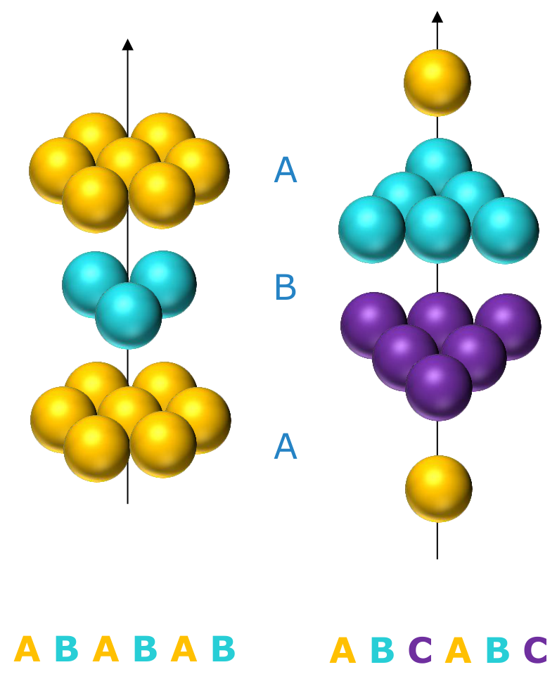
Stacking close-packed layers can be done in two ways, because the third layer has two choices of hollows to sit in:
- A B A B … : the third layer sits exactly over the first. This is the hexagonal close-packed (HCP) structure.
- A B C A B C … : the third layer sits over neither of the first two; only the fourth repeats the first. This is the face-centred cubic (FCC) structure.
§ 7 Main metallic structures [Session 3 Slides 24-28]
About 90 % of metals crystallize in one of three densely packed structures. They do so because:
- a pure metal is made of atoms of one element, so all atoms have the same radius;
- the metallic bond is non-directional, so atoms simply pack as closely as they can;
- smaller distances between atoms give higher lattice energies, so dense packing is the arrangement of minimum energy.
| Structure | Examples |
|---|---|
| Body-centred cubic (BCC) | Fe, Cr, Mo, V, W, K |
| Face-centred cubic (FCC) | Al, Cu, Pb, Ni, Pt, Ag |
| Hexagonal close-packed (HCP) | Ti, Mg, Cd, Co, Zn |
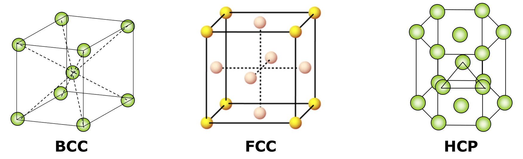
To compare them we use three numbers: how many atoms belong to one cell, how many neighbours each atom touches (the coordination number), and how much of the cell volume the atoms fill:
Counting atoms per cell. An atom at a corner is shared by the 8 cells that meet there, so only ⅛ of it belongs to each cell. An atom on a face is shared by 2 cells (½ each). An atom inside the cell belongs to it completely.
7.1 Body-centred cubic (BCC) [Session 3 Slide 26]
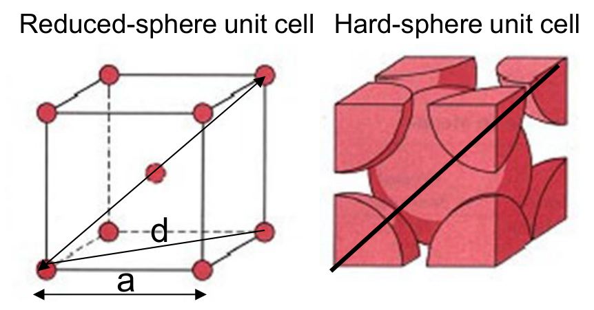
- Atoms per cell: 8 corners × ⅛ + 1 centre = 2 atoms.
- Coordination number: 8 (the central atom touches the 8 corners).
- Where atoms touch: along the body diagonal of the cube. The face diagonal is $d$, with $d^2 = a^2 + a^2 = 2a^2$; the body diagonal $D$ satisfies $D^2 = a^2 + d^2 = 3a^2$, so $D = \sqrt3\,a$. Along it lie a corner atom, the central atom and the opposite corner atom: $D = 4R$. Therefore
- Packing factor:
68 % of the cell is occupied by atoms.
7.2 Face-centred cubic (FCC) [Session 3 Slide 27]
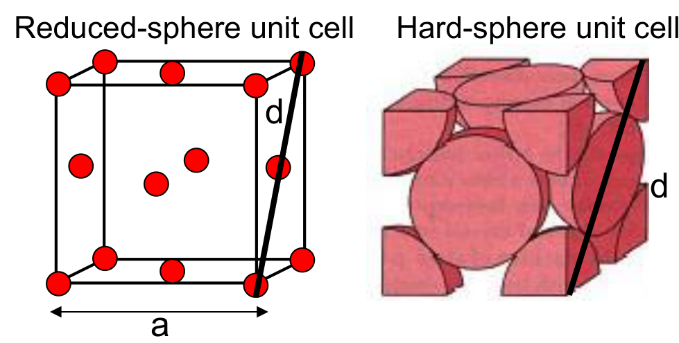
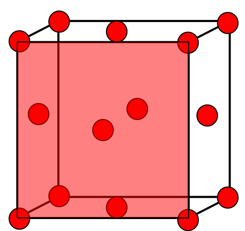
- Atoms per cell: 8 corners × ⅛ + 6 faces × ½ = 4 atoms.
- Coordination number: 12.
- Where atoms touch: along the face diagonal: a corner atom, the face-centre atom and the opposite corner atom, so $d = 4R$. With $d^2 = a^2 + a^2$, $d = \sqrt2\,a$:
- Packing factor:
74 % of the cell is occupied: FCC is a close-packed structure.
7.3 Hexagonal close-packed (HCP) [Session 3 Slide 28]
- Atoms per cell: 12 corners × ⅙ + 2 base centres × ½ + 3 inside = 6 atoms (each corner of the hexagonal prism is shared by 6 cells).
- Coordination number: 12.
- Geometry: atoms touch along the edge of the hexagon, so $2R = a$. The height of the cell is $c = \frac{2\sqrt2}{\sqrt3}\,a$.
- Volume: the base is a hexagon made of 6 equilateral triangles of side $a$: $B = 3\cdot\frac{\sqrt3}{2}a^2$. Then
- Packing factor:
Like FCC, 74 % of the cell is occupied. That is expected: FCC and HCP are the two ways of stacking the same close-packed layers.
§ 8 Interstitial sites [Session 3 Slides 30-35]
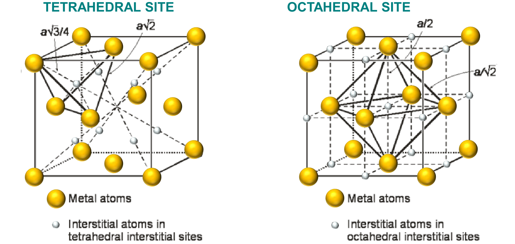
Even in the densest packing, 26 % of the volume is empty. The gaps between the regular atom positions are interstitial sites: places that other (usually smaller) atoms or ions can occupy. There are two kinds:
- tetrahedral site: surrounded by 4 lattice atoms (at the corners of a tetrahedron);
- octahedral site: surrounded by 6 lattice atoms (at the corners of an octahedron).
In compact structures, with $n$ atoms per cell:
FCC ($n = 4$):
- tetrahedral: 8 sites completely inside the cell, 8 × 1 = 8;
- octahedral: 1 at the centre of the cell, plus 12 at the middle of the edges, each shared by 4 cells: 1 + 12 × ¼ = 4.
BCC ($n = 2$):
- tetrahedral: 4 on each of the 6 faces, each shared by 2 cells: 6 × 4 × ½ = 12;
- octahedral: one at the centre of each face (6 × ½ = 3) plus one at the middle of each edge (12 × ¼ = 3): 6.
HCP ($n = 6$): 12 tetrahedral and 6 octahedral sites.
| Structure | Atoms per cell | Tetrahedral sites | Octahedral sites |
|---|---|---|---|
| FCC | 4 | 8 | 4 |
| HCP | 6 | 12 | 6 |
| BCC | 2 | 12 | 6 |
BCC is not close-packed, so the rule $2n$ / $n$ does not apply to it.
For BCC, the 3 octahedral sites counted as "6 × ½" are labelled "center"; they are the centres of the 6 faces (each shared by 2 cells), not the centre of the cube.
§ 9 Atomic positions [Session 3 Slide 37]
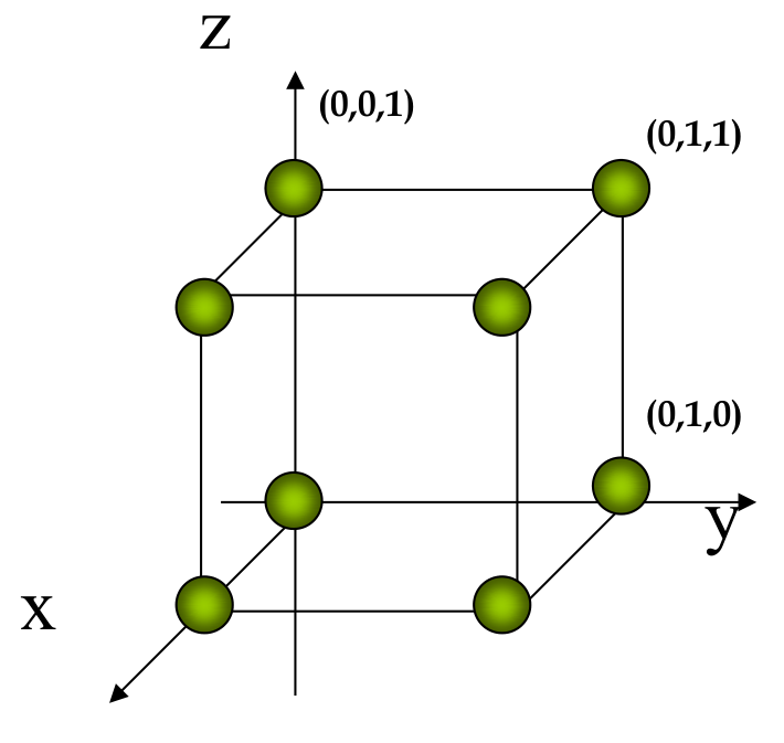
In an orthogonal lattice (all angles 90°), the three lattice vectors define every point of the cell without ambiguity, so they can be used to give the position of each atom. In a cubic cell ($a = b = c$) a position is written as three coordinates, each a fraction of the edge between 0 and 1:
The origin is $(0,0,0)$; the corner along $y$ is $(0,1,0)$; the top corner above the origin is $(0,0,1)$; the corner opposite the origin is $(1,1,1)$; the centre of the cube is $(\tfrac12, \tfrac12, \tfrac12)$.
§ 10 Directions in the cubic cell [Session 3 Slides 39-42]
10.1 What a direction is
A crystallographic direction is a vector joining two points of the lattice. It is written with square brackets and no commas, $[u\,v\,w]$. The indices $u, v, w$ are the components of the vector along the three axes, reduced to the smallest integers that keep the same ratio.
Two vectors that are parallel have the same indices: a direction does not depend on where it starts, only on where it points. For that reason any direction can be drawn starting at a corner of the cell.
Negative components are written with a bar over the number: $[\bar u\,v\,w]$ means $u$ is negative. ($[\bar1\,1\,0]$ is read "minus one, one, zero".)
10.2 How to draw a direction from its indices
- Choose the origin. Normally $O = (0,0,0)$. If an index is negative, use a new origin $O'$ (see 10.3).
- Scale the indices so that the largest becomes 1. This keeps the arrow inside the cell. Example: $[0\,1\,2] \to \tfrac12[0\,1\,2] = [0, \tfrac12, 1]$.
- Locate the tip: start at the origin and move those amounts along $x$, $y$ and $z$.
- Draw the arrow from the origin to the tip.
Example 1: $[1\,0\,0]$, $[1\,1\,0]$, $[1\,1\,1]$. The largest index is already 1, so the tips are directly $(1,0,0)$, $(1,1,0)$ and $(1,1,1)$: a cube edge, a face diagonal and the body diagonal.
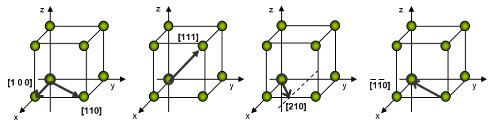
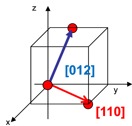
Example 2: $[0\,1\,2]$.
- Origin $O = (0,0,0)$ (no negative indices).
- Largest index 2, divide by 2: $[0, \tfrac12, 1]$.
- Tip at $x = 0$, $y = \tfrac12$, $z = 1$: the middle of the top edge on the back face.
- Arrow from $(0,0,0)$ to $(0, \tfrac12, 1)$.
Example 3: $[2\,1\,0]$. Divide by 2: $[1, \tfrac12, 0]$. The arrow goes from the origin to the middle of the bottom edge on the front face, $(1, \tfrac12, 0)$. It lies in the bottom face because $w = 0$. It is the third small cube of the Slide 39 figure shown under Example 1.
Example 4: $[1\,2\,2]$. Divide by 2: $[\tfrac12, 1, 1]$. The tip is at the middle of the top edge on the right face, $(\tfrac12, 1, 1)$.
10.3 Directions with negative indices
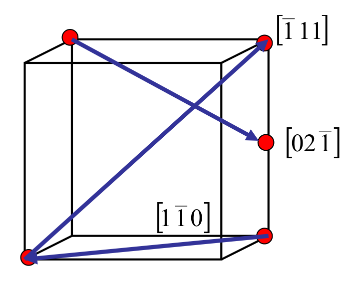
If an index is negative, the arrow would leave the cell when drawn from $(0,0,0)$. To keep it inside, move the origin: the new origin $O'$ has a 1 where the index is negative and a 0 where it is positive (or zero). Then draw the arrow from $O'$ as usual.
| Direction | New origin $O'$ | Tip ($O'$ + scaled indices) |
|---|---|---|
| $[\bar1\,1\,1]$ | $(1,0,0)$ | $(1-1,\ 0+1,\ 0+1) = (0,1,1)$ |
| $[1\,\bar1\,0]$ | $(0,1,0)$ | $(0+1,\ 1-1,\ 0) = (1,0,0)$ |
| $[0\,2\,\bar1]$ | $(0,0,1)$ | scaled $[0, 1, -\tfrac12]$: $(0,\ 1,\ 1-\tfrac12) = (0,1,\tfrac12)$ |
Example 5: $[\bar1\,2\,2]$. The $u$ index is negative, so $O' = (1,0,0)$. Scale by ½: $[-\tfrac12, 1, 1]$. Tip $= (1-\tfrac12,\ 0+1,\ 0+1) = (\tfrac12, 1, 1)$. The arrow goes from the front-bottom-left corner $(1,0,0)$ up to the middle of the top edge on the right face.
10.4 How to read the indices of a drawn direction
- Take a vector along the direction that passes through the origin (or any parallel copy of it: parallel vectors have the same indices).
- Measure its projections on the three axes, in units of the cell edges $a$, $b$, $c$. In practice: coordinates of the head minus coordinates of the tail.
- Multiply or divide by a common factor to reach the smallest integers.
- Write them in square brackets without commas, with a bar over any negative number.
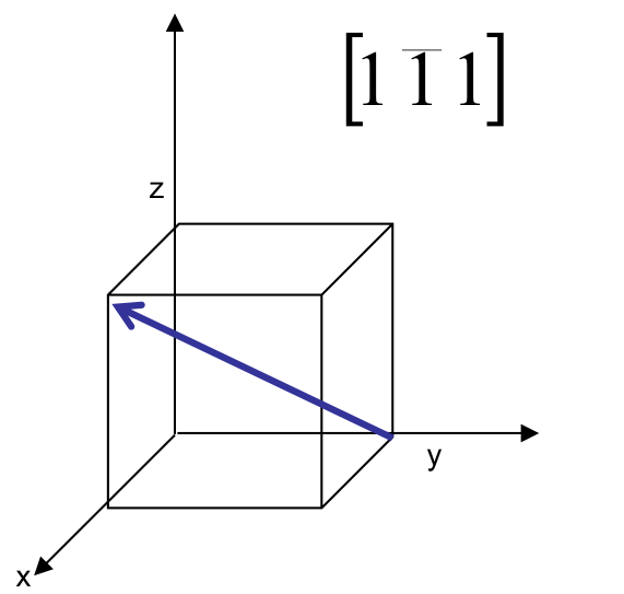
Example 6 [Session 3 Slide 41]. A vector goes from the tail $(0,1,0)$ to the head $(1,0,1)$. Head − tail $= (1-0,\ 0-1,\ 1-0) = (1, -1, 1)$. They are already the smallest integers, so the direction is $[1\,\bar1\,1]$.
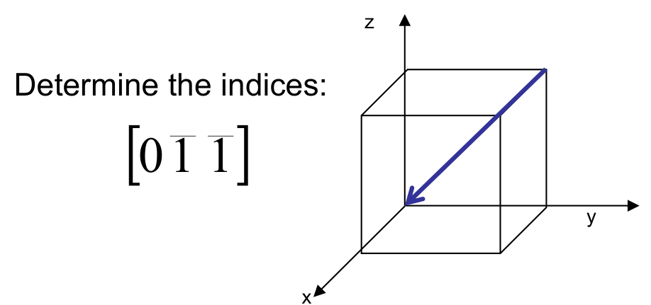
Example 7 [Session 3 Slide 41]. A vector goes from $(0,1,1)$ to $(0,0,0)$. Head − tail $= (0, -1, -1)$: the direction is $[0\,\bar1\,\bar1]$. Its opposite, from $(0,0,0)$ to $(0,1,1)$, is $[0\,1\,1]$: reversing an arrow changes the sign of every index.
Example 8. A vector goes from $(0,0,0)$ to $(\tfrac12, 1, 0)$. Head − tail $= (\tfrac12, 1, 0)$. Multiply by 2 to clear the fraction: $[1\,2\,0]$.
10.5 Families of directions
Directions that are equivalent in the lattice (the atoms are spaced the same way along them) form a family, written with angle brackets $\langle u\,v\,w\rangle$. In a cube:
- Cube edges: $[100], [010], [001], [\bar100], [0\bar10], [00\bar1]$ form $\langle 100\rangle$.
- Face diagonals: $\langle 110\rangle$.
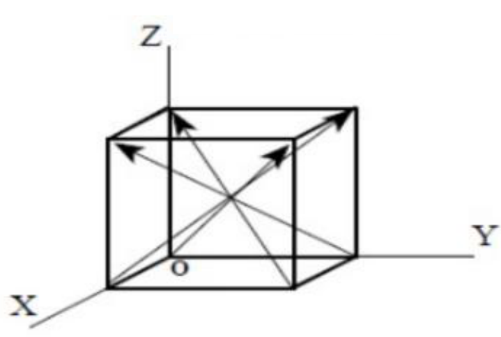
- Body diagonals: $\langle 111\rangle$: the four diagonals $[111], [\bar111], [1\bar11], [11\bar1]$ (each with its opposite).
§ 11 Planes in the cubic cell [Session 3 Slides 44-50]
11.1 Miller indices of a plane
A crystallographic plane is described by its Miller indices $(h\,k\,l)$, written in round brackets and no commas. They are the reciprocals of the points where the plane cuts the axes $x$, $y$ and $z$ (measured in units of $a$, $b$, $c$):
A plane parallel to an axis never cuts it: its intercept is $\infty$, and $1/\infty = 0$. So a zero index always means "parallel to that axis".
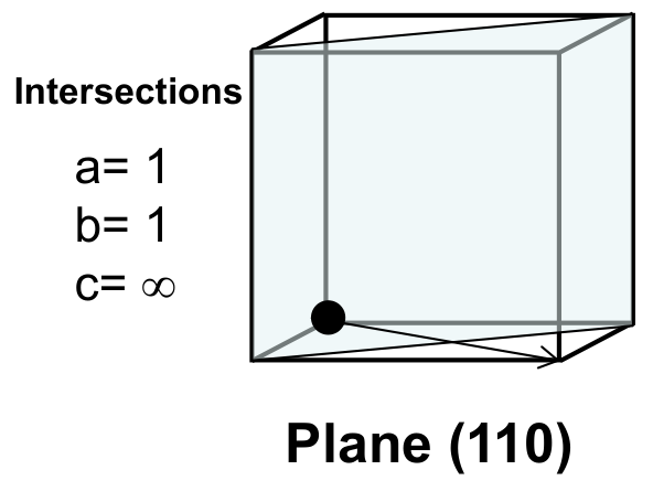
Example: a plane that cuts $x$ at 1 and $y$ at 1 and is parallel to $z$ has intercepts $(1, 1, \infty)$, reciprocals $(1, 1, 0)$: it is the plane $(1\,1\,0)$.
11.2 How to find the indices of a drawn plane
- Choose the origin $O$. The plane must not pass through it; if it does, use the nearest other corner.
- Find the intercepts of the plane with the three axes.
- Take their reciprocals.
- Reduce them to the smallest integers with the same ratio.
- Write them in parentheses without commas: $(h\,k\,l)$.
| Intercepts $x, y, z$ | Reciprocals | Plane |
|---|---|---|
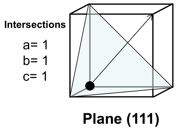
| $1,\ 1,\ 1$ | $1,\ 1,\ 1$ | $(1\,1\,1)$ |
| $1,\ 1,\ \infty$ | $1,\ 1,\ 0$ | $(1\,1\,0)$ |
| $1,\ \infty,\ \infty$ | $1,\ 0,\ 0$ | $(1\,0\,0)$ |
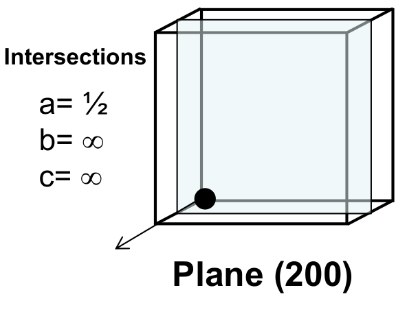
| $\tfrac12,\ \infty,\ \infty$ | $2,\ 0,\ 0$ | $(2\,0\,0)$ |
| $\tfrac12,\ 1,\ \infty$ | $2,\ 1,\ 0$ | $(2\,1\,0)$ |
| $\infty,\ 1,\ 1$ | $0,\ 1,\ 1$ | $(0\,1\,1)$ |
Example 1: $(1\,0\,0)$, $(1\,1\,0)$, $(1\,1\,1)$.
- $(1\,0\,0)$ cuts only $x$, at 1, and is parallel to $y$ and $z$: it is the front face of the cube.
- $(1\,1\,0)$ cuts $x$ at 1 and $y$ at 1 and is parallel to $z$: a vertical diagonal plane through two opposite vertical edges.
- $(1\,1\,1)$ cuts all three axes at 1: the triangle joining $(1,0,0)$, $(0,1,0)$ and $(0,0,1)$.
Example 2: $(2\,0\,0)$, $(2\,1\,0)$, $(0\,1\,1)$.
- $(2\,0\,0)$: intercept on $x$ is $\tfrac12$, parallel to $y$ and $z$. It has the same orientation as $(1\,0\,0)$ but cuts the cell half way; here the index is kept as 2 to show that position.
- $(2\,1\,0)$: intercepts $x = \tfrac12$, $y = 1$, parallel to $z$. A vertical plane that cuts the left face ($y = 0$) along the line $x = \tfrac12$ and reaches the back-right vertical edge ($x = 0$, $y = 1$).
- $(0\,1\,1)$: parallel to $x$, cuts $y$ and $z$ at 1. A tilted plane that runs along $x$, from the top edge of the left face ($y = 0$, $z = 1$) down to the bottom edge of the right face ($y = 1$, $z = 0$).
11.3 How to draw a plane from its indices
- Choose the origin: $O = (0,0,0)$, or $O'$ if any index is negative (see 11.4).
- Take the reciprocals of the indices, $1/h$, $1/k$, $1/l$: these are the intercepts.
- Mark the intercepts on the axes ($1/0 = \infty$ means the plane does not cut that axis: it is parallel to it).
- Join the intercepts to draw the plane.
Example 3: $(0\,1\,1)$.
- No negative indices: $O = (0,0,0)$.
- Intercepts: $x = 1/0 = \infty$, $y = 1/1 = 1$, $z = 1/1 = 1$.
- The plane is parallel to $x$ and passes through $(0,1,0)$ and $(0,0,1)$.
- Because it is parallel to $x$, slide that line along $x$: the plane is the rectangle with corners $(0,1,0)$, $(0,0,1)$, $(1,0,1)$, $(1,1,0)$.
11.4 Planes with negative indices
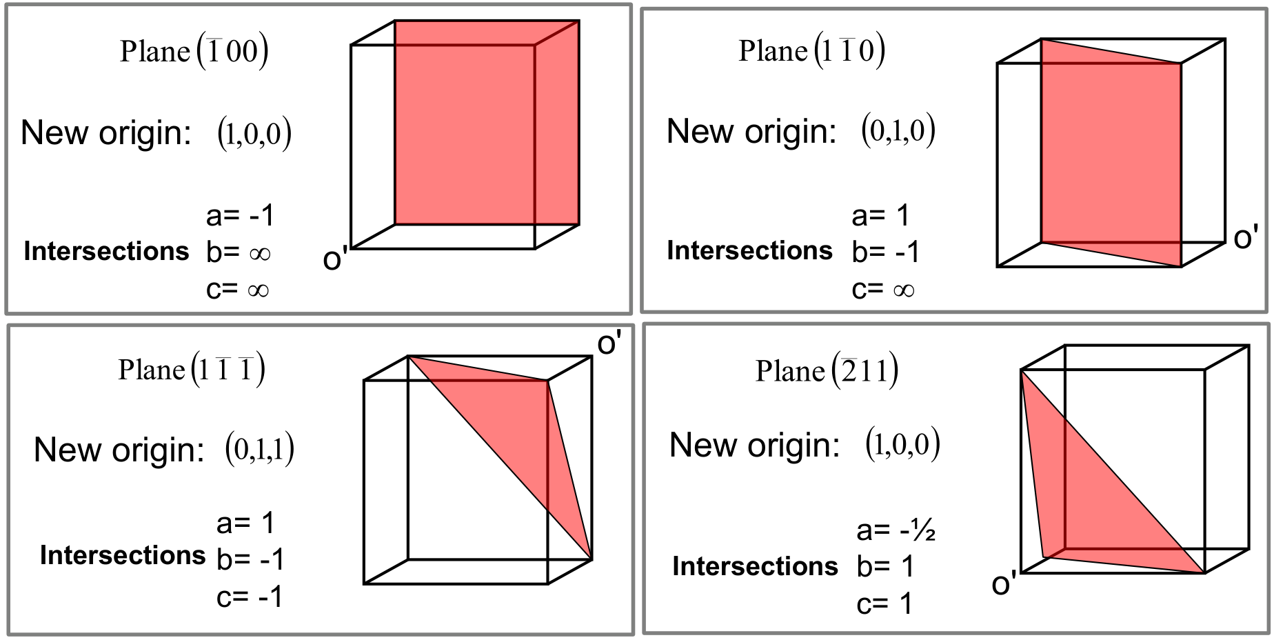
To draw a plane with a negative index inside the cell, move the origin in the direction of that index: as with directions, $O'$ has a 1 in the position of each negative index and a 0 elsewhere. The intercepts are then measured from $O'$, and a negative intercept means going backwards along that axis.
| Plane | New origin $O'$ | Intercepts from $O'$ | Result |
|---|---|---|---|
| $(\bar1\,0\,0)$ | $(1,0,0)$ | $x = -1$, $y = \infty$, $z = \infty$ | the back face $x = 0$ |
| $(1\,\bar1\,0)$ | $(0,1,0)$ | $x = 1$, $y = -1$, $z = \infty$ | vertical diagonal plane through the edges at $(0,0)$ and $(1,1)$ |
| $(1\,\bar1\,\bar1)$ | $(0,1,1)$ | $x = 1$, $y = -1$, $z = -1$ | triangle through $(1,1,1)$, $(0,0,1)$ and $(0,1,0)$ |
| $(\bar2\,1\,1)$ | $(1,0,0)$ | $x = -\tfrac12$, $y = 1$, $z = 1$ | triangle through $(\tfrac12,0,0)$, $(1,1,0)$ and $(1,0,1)$ |
Example 4: $(1\,\bar1\,\bar1)$, step by step.
- Negative indices in $y$ and $z$: $O' = (0,1,1)$.
- Intercepts from $O'$: $x = 1/1 = 1$, $y = 1/(-1) = -1$, $z = 1/(-1) = -1$.
- From $O' = (0,1,1)$: one unit forward in $x$ gives $(1,1,1)$; one unit back in $y$ gives $(0,0,1)$; one unit back in $z$ gives $(0,1,0)$.
- The plane is the triangle joining those three points.
Example 5: $(\bar2\,1\,1)$, step by step.
- Negative index in $x$: $O' = (1,0,0)$.
- Intercepts from $O'$: $x = 1/(-2) = -\tfrac12$, $y = 1$, $z = 1$.
- From $(1,0,0)$: half a unit back in $x$ gives $(\tfrac12,0,0)$; one unit in $y$ gives $(1,1,0)$; one unit in $z$ gives $(1,0,1)$.
- Join the three points.
11.5 Families of planes
- Parallel, equally spaced planes have the same Miller indices.
- Planes that are equivalent in the lattice (with the same arrangement of atoms) form a family, written with curly brackets $\{h\,k\,l\}$.
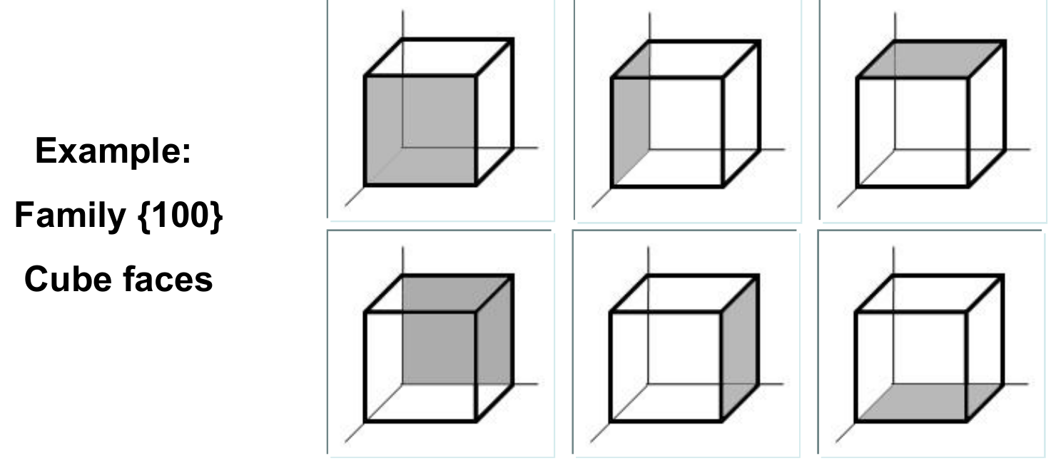
11.6 Directions and planes with the same indices
In cubic lattices, a direction is perpendicular to the plane with the same indices: $[1\,1\,1] \perp (1\,1\,1)$, $[1\,0\,0] \perp (1\,0\,0)$, $[1\,1\,0] \perp (1\,1\,0)$. This only holds for cubic cells.
§ 12 Directions and planes in the hexagonal cell [Session 3 Slides 51-52]
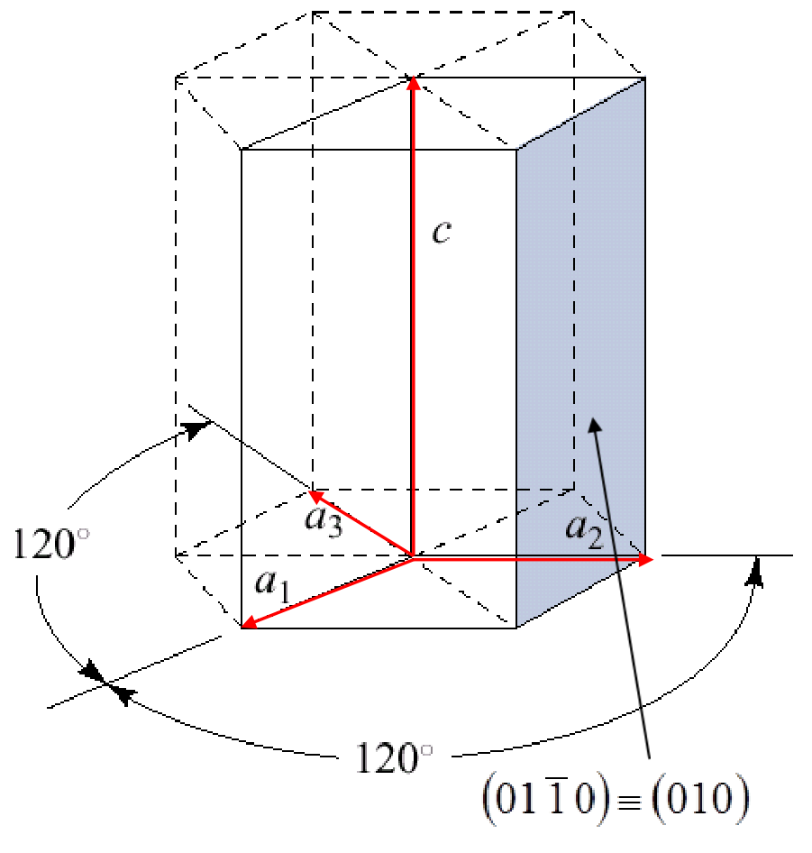
The hexagonal cell is described with four axes: three in the basal plane, $a_1$, $a_2$, $a_3$, at 120° from each other, and the vertical axis $c$. Indices therefore have four numbers: $h$, $k$, $i$ for the three basal axes and $l$ for $c$.
Planes. Only three of the four indices are independent, because the three basal axes are related:
So a plane written with three indices $(h'\,k'\,l')$ becomes $(h\,k\,i\,l)$ by adding $i$. Example: $(0\,1\,0) \equiv (0\,1\,\bar1\,0)$, since $i = -(0 + 1) = -1$. This plane is a side face of the prism, parallel to $a_1$ and to $c$.
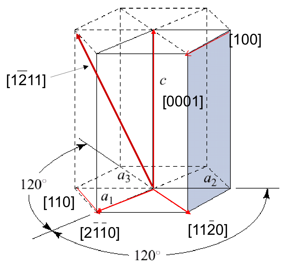
Directions. A direction $[h'\,k'\,l']$ written in three indices becomes $[h\,k\,i\,l]$ with
and the result is then reduced to integers.
Example: $[1\,0\,0]$. $h = \tfrac13(2\cdot1 - 0) = \tfrac23$, $k = \tfrac13(2\cdot0 - 1) = -\tfrac13$, $i = -\tfrac13(1 + 0) = -\tfrac13$, $l = 0$. Multiplying by 3: $[1\,0\,0] \equiv [2\,\bar1\,\bar1\,0]$, along $a_1$.
Example: $[1\,1\,0]$. $h = \tfrac13(2 - 1) = \tfrac13$, $k = \tfrac13(2 - 1) = \tfrac13$, $i = -\tfrac13(1 + 1) = -\tfrac23$, $l = 0$. Multiplying by 3: $[1\,1\,0] \equiv [1\,1\,\bar2\,0]$.
Example: $[0\,0\,1]$. $h = k = i = 0$ and $l = 1$: $[0\,0\,0\,1]$, along $c$.
The conversion rule for the fourth index is printed as $l = -l'$. With that sign, the vertical direction $[0\,0\,1]$ would become $[0\,0\,0\,\bar1]$, pointing down, while the same material labels it $[0\,0\,0\,1]$. The rule is $l = l'$.
§ 13 Spacing between parallel planes [Session 3 Slide 53]
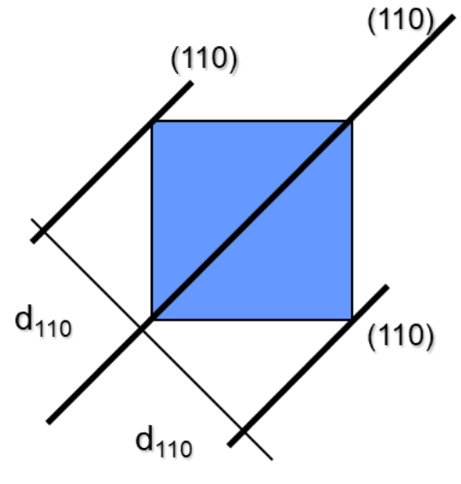
The interplanar spacing $d_{hkl}$ is the distance between two neighbouring parallel planes $(h\,k\,l)$. It depends on the Miller indices and on the lattice parameters.
Cubic crystals:
Example: for $(1\,1\,0)$, $d_{110} = a/\sqrt{1 + 1 + 0} = a/\sqrt2$.
Orthogonal crystals in general (all angles 90°, edges $a$, $b$, $c$):
With $a = b = c$ this reduces to the cubic formula.
Part II: Densities and crystalline defects
§ 14 Atomic densities [Session 4 Slides 7-9]
14.1 Volume density [Session 4 Slide 7]
$n$ = atoms per cell, $M$ = atomic weight, $V_{cell}$ = volume of the cell, $N_A$ = Avogadro's number ($6.023\times10^{23}$ atoms/mol). Dividing only the number of atoms by the volume gives the number of atoms per unit volume, $\rho_V = n/V_{cell}$.
Example: copper (FCC), $M = 63.5$ g/mol, $R = 1.28$ Å $= 1.28\times10^{-8}$ cm.
- Atoms per cell: $n = 8\cdot\tfrac18 + 6\cdot\tfrac12 = 4$.
- Edge: $a = 2\sqrt2\,R$, so $V_{cell} = a^3 = (2\sqrt2\,R)^3 = 16\sqrt2\,R^3$.
- Atoms per volume: $\rho_V = \dfrac{4}{(2\sqrt2\cdot1.28\times10^{-8}\ \text{cm})^3} = 8.43\times10^{22}\ \text{atoms/cm}^3$.
- Density: $\rho = \dfrac{4\cdot63.5\ \text{g/mol}}{6.023\times10^{23}\ \text{atoms/mol}}\cdot\dfrac{1}{V_{cell}} = 8.89\ \text{g/cm}^3$.
14.2 Linear density [Session 4 Slide 8]
Only atoms cut through their centre by the line count, and an atom at the end of the segment counts ½ (it is shared with the next segment).
Example: Cu (FCC), direction $[1\,0\,0]$. The cube edge has an atom at each end: 2 × ½ = 1 atom, over the length $a = 2\sqrt2\,R$:
Example: Cu (FCC), direction $[1\,1\,1]$. The body diagonal has length $\sqrt3\,a$. In an FCC cell no atom sits at the centre of the cube, so the only atoms on this line are the two corners: 2 × ½ = 1 atom:
The official example counts "1 central atom + 2 · ½ vertices" along $[1\,1\,1]$ in FCC copper, giving $2/(\sqrt3\,a) = 2\sqrt3/(3a)$. A centre atom only exists in BCC. In FCC the face-centre atoms (such as $(\tfrac12, \tfrac12, 0)$) do not lie on the line $(t, t, t)$, so the count is 1 atom and $\rho_{[111]} = 1/(\sqrt3\,a)$.
14.3 Planar density [Session 4 Slide 9]
Example: Cu (FCC), plane $(1\,0\,0)$. The plane is a cube face: 1 atom at its centre plus 4 corners, each shared by 4 faces (¼ each): 1 + 4 · ¼ = 2 atoms, over the area $a^2$:
14.4 Summary of the three structures [Session 4 Slide 10]
| FCC | BCC | HCP | |
|---|---|---|---|
| Atoms per cell | $8\cdot\tfrac18 + 6\cdot\tfrac12 = 4$ | $8\cdot\tfrac18 + 1 = 2$ | $12\cdot\tfrac16 + 2\cdot\tfrac12 + 3 = 6$ |
| Atomic radius | $r = \dfrac{a}{2\sqrt2}$ | $r = \dfrac{a\sqrt3}{4}$ | $r = \tfrac12\sqrt{\dfrac{a^2}{3} + \dfrac{c^2}{4}}$ |
| Cell volume | $a^3$ | $a^3$ | $a^2 c\,\dfrac{3\sqrt3}{2}$ |
| Empty volume $V_h = V_c - V_{atoms}$ | $5.872\,r^3$ | $3.94\,r^3$ | $8.808\,r^3$ |
| Empty fraction $V_h/V_c$ | 0.26 | 0.32 | 0.26 |
| Octahedral sites | 4, radius $\tfrac12(a - 2r) = 0.41\,r$ | 6, radius $\tfrac12(a - 2r) = 0.15\,r$ | 6, radius $0.41\,r$ |
| Tetrahedral sites | 8, radius $\left(\sqrt{\tfrac32} - 1\right)r = 0.225\,r$ | 12, radius $\left(\sqrt{\tfrac53} - 1\right)r = 0.291\,r$ | 12, radius $0.225\,r$ |
| Close-packed planes | $\{111\}$: 4 | $\{110\}$: 6 | $\{0001\}$: 1 |
| Close-packed directions | $\langle110\rangle$: 6 | $\langle111\rangle$: 4 | $\langle2\bar1\bar10\rangle$: 3 |
The empty fractions match the packing factors: $1 - 0.74 = 0.26$ and $1 - 0.68 = 0.32$.
§ 15 Perfect and real crystals [Session 4 Slides 12-13]
A perfect crystal has every atom in its regular position, the same spacing $d_{hkl}$ everywhere for each set of planes, and no missing or extra atoms. It could only exist at 0 K.
A real crystal is different: its atoms vibrate, some positions are empty (vacancies), some atoms are displaced from their ideal positions, and these defects change the properties.
A crystalline defect is any disruption of the perfect periodic arrangement of atoms or ions.
Why defects always exist. Creating a defect costs energy (its enthalpy $\Delta H$ is positive) but it also increases disorder (its entropy $\Delta S$ is positive). The crystal settles where its Gibbs energy is lowest:
A defect forms when it lowers $G$, that is when $\Delta G < 0$, or $\Delta H < T\Delta S$. The equilibrium number of defects is where $G$ stops decreasing ($\Delta G = 0$): beyond it, extra defects would cost more energy than the disorder they add.
The entropy comes from the number of ways $W$ of placing $n$ defects among $N$ possible positions:
with $k_B = 1.380622\times10^{-23}$ J/K, the Boltzmann constant. In one mole of a crystal there are $N_A$ possible places for a single vacancy, so $W \sim 10^{23}$ even for one defect: the gain in entropy is large. Because the $T\Delta S$ term grows with temperature, the number of defects increases with temperature.
§ 16 Types of defects [Session 4 Slide 14]
Defects are classified by their dimension:
| Type | Examples |
|---|---|
| 1. Point (0-D) | vacancies, interstitials, substitutional atoms, Schottky and Frenkel defects, order-disorder |
| 2. Linear (1-D): dislocations | edge (Taylor), screw (Burgers), mixed |
| 3. Planar or extended (2-D) | external surfaces, grain boundaries, twin boundaries, stacking faults |
| 4. Complex (volume, 3-D) | clusters |
§ 17 Point defects [Session 4 Slides 15-18]
17.1 What they are [Session 4 Slide 15]
Point defects are local disruptions of an otherwise perfect arrangement. Although they occupy only one or two sites, their effect is felt over much larger distances in the crystal. They appear when atoms move after gaining energy (for example, when the temperature rises). Foreign atoms can also act as point defects:
- impurities: elements or compounds that come from the raw materials or the processing;
- dopants: elements or compounds added on purpose, in known amounts.
17.2 Vacancies and interstitials [Session 4 Slide 16]
- Interstitial: an atom of the crystal sits in an interstitial site instead of a regular one (self-interstitial or interstitialcy).
- Vacancy: an atom is missing from its regular position.
The number of vacancies at temperature $T$ is
| Symbol | Meaning |
|---|---|
| $n_v$ | vacancies per cm³ |
| $N$ | lattice points per cm³ |
| $\Delta H_v$ | energy to form one mole of vacancies (J/mol) |
| $n_v/N$ | fraction of vacant sites |
| $N_A$, $M$, $\rho$ | Avogadro's number, atomic (molecular) weight, density |
In metals at equilibrium the fraction of vacancies reaches at most about $n_v/N \approx 10^{-4}$.
Vacancies are produced during solidification (impurities, alloys), by bombarding with high-energy particles, during plastic deformation (processing), and simply by heating: higher temperature → stronger thermal vibrations → more vacancies.
17.3 Schottky and Frenkel defects in ionic crystals [Session 4 Slides 17-18]
In an ionic crystal, removing a single ion would leave the crystal electrically charged. Defects therefore come in combinations that keep it neutral:
- Schottky defect: a pair of vacancies of opposite charge, one cationic and one anionic.
- Frenkel defect: an ion moves from its regular position to an interstitial site, leaving a vacancy behind (a vacancy-interstitial pair).
$\Delta H_S$ and $\Delta H_F$ are the energies needed to create each defect, $N$ the number of lattice positions, $N_i$ the number of interstitial positions, $T$ the temperature in kelvin. In a given crystal $\Delta H_S \neq \Delta H_F$, and the defect with the lower energy is the one that forms.
Example: Schottky defects in NaCl and MgO.
| Crystal | $\Delta H_S$ (J per defect) | $n_S$ at 300 K (per mol) | $n_S$ at 1000 K (per mol) |
|---|---|---|---|
| NaCl | $3.69\times10^{-19}$ | $2.64\times10^{4}$ | $9.38\times10^{17}$ |
| MgO | $10.57\times10^{-19}$ | $2.12\times10^{-32}$ | $1.39\times10^{7}$ |
Two conclusions: the number of defects rises enormously with temperature, and because $\Delta H_S$(MgO) > $\Delta H_S$(NaCl), vacancies are much harder to create in MgO.
Here the energy is given per defect, so the gas constant $R$ is replaced by the Boltzmann constant $k_B$: $\dfrac{\Delta H_S}{2k_BT} = \dfrac{3.69\times10^{-19}}{2\cdot1.38\times10^{-23}\cdot300} = 44.6$, and $n_S = 6.02\times10^{23}\cdot e^{-44.6} \approx 2.6\times10^{4}$ per mol.
§ 18 Solid solutions [Session 4 Slides 19, 21-24]
18.1 What a solid solution is [Session 4 Slide 21]
When two materials are mixed as liquids and then solidified, the result is either a new phase or a solid solution.
A solid solution is a crystalline solid with two or more elements dispersed as atoms in a structure that has a single phase. There are two kinds:
- substitutional: the solute atoms replace atoms of the host;
- interstitial: the solute atoms sit in the interstitial sites of the host. Only small atoms can do this: H, C, N, B.
18.2 Defects created by a solid solution in ionic solids [Session 4 Slide 22]
When MgO and Al₂O₃ form a solid solution, Al³⁺ ions replace Mg²⁺ ions in the MgO crystal. Each Al³⁺ carries one more positive charge than the Mg²⁺ it replaces, so to keep the crystal neutral some cation sites must stay empty. Three Mg²⁺ (total charge +6) are replaced by two Al³⁺ (also +6) and one vacancy:
18.3 Hume-Rothery rules [Session 4 Slide 23]
The conditions for forming a solid solution:
Substitutional solid solutions:
- solute and solvent must have the same crystal structure;
- their atomic radii must be similar: difference below 30 % for ceramics and below 15 % for metals; above 15 %, solubility is limited (< 1 %);
- they must have similar electronegativities;
- they must have the same valence.
Interstitial solid solutions:
- the solute atoms must be smaller than the solvent atoms;
- they must have similar electronegativities.
Meeting all the conditions does not guarantee complete solubility; failing one or more of them gives partial solubility.
18.4 Order and disorder [Session 4 Slides 19, 24]
In substitutional solid solutions of elements with similar electronegativities, the two kinds of atoms can be arranged in two ways:
- disorder: atoms of one kind occupy the positions of the other, and vice versa, at random;
- order: above or below a critical temperature, the atoms return to regular positions, each kind on its own sub-lattice.
Example: the Cu-Au alloy is disordered above 390 °C and ordered below 390 °C.
§ 19 Linear defects: dislocations [Session 4 Slides 26-37]
19.1 What a dislocation is [Session 4 Slide 26]
A dislocation is a line imperfection in an otherwise perfect crystal. Dislocations can move through the crystal under relatively small forces, and their movement can shift whole crystal planes past each other. They explain:
- why the measured strength and stiffness are lower than the theoretical values;
- plastic deformation of metals (their workability and ductility).
They form during solidification, during plastic (permanent) deformation, from concentrations of vacancies, and from atomic disorder in solid solutions. There are three types: edge (Taylor), screw (Burgers) and mixed.
19.2 Edge dislocation [Session 4 Slides 29-30]
An edge dislocation is equivalent to inserting an extra half-plane of atoms into the crystal. It distorts the lattice and stores energy.
It is characterized by the Burgers vector b: the magnitude and direction of the lattice distortion caused by the dislocation. To find it, draw a loop around the dislocation taking the same number of atom spacings in each direction; around a perfect crystal the loop would close, but around a dislocation it does not, and b is the vector needed to close it.
For an edge dislocation:
- b is perpendicular to the dislocation line;
- b is parallel to the direction of movement;
- the energy stored grows with the square of its size: $E \propto |\vec b|^2$.
19.3 Screw dislocation [Session 4 Slide 31]
A screw dislocation bends some lines of atoms locally, as if a shear stress had been applied to one part of the crystal. Following the atoms around the dislocation line traces a spiral ramp (a screw). The Burgers vector is again the vector that closes a loop around it, and:
- b is parallel to the dislocation line;
- b is perpendicular to the direction of movement.
19.4 Mixed dislocation [Session 4 Slide 32]
Real dislocations are usually mixed: they change gradually from edge to screw character, with a transition region between the two. The Burgers vector is the same along the whole dislocation.
19.5 How dislocations move [Session 4 Slides 33-37]
A metal can be deformed plastically only if its dislocations can move; its strength and ductility depend on how easily they move.
Slip is the process by which plastic deformation happens through the motion of dislocations:
- the dislocation moves along a slip direction on a slip plane;
- the slip direction and the slip plane together form a slip system;
- for an edge dislocation, b is parallel to the slip direction;
- for a screw dislocation, b is perpendicular to the slip direction;
- the slip direction is the direction of maximum packing (highest linear density).
Why the densest direction: the energy needed to move a dislocation is $E \propto |\vec b|^2$, and the shortest Burgers vector is found along the close-packed direction. In FCC:
- along the close-packed direction $[1\,1\,0]$, atoms touch, so $b = 2R$ and $E \propto 4R^2$;
- along $[1\,0\,0]$, which is not close-packed, the cube edge is $b$, and the face diagonal of length $4R$ gives $b^2 + b^2 = (4R)^2$, so $b = 2\sqrt2\,R$ and $E \propto 8R^2$.
Slip along $[1\,1\,0]$ costs half the energy.
Slip systems of the three structures:
| Structure | Slip plane | Slip direction | Number of slip systems |
|---|---|---|---|
| BCC | $\{110\}$ | $\langle\bar111\rangle$ | 6 × 2 = 12 |
| FCC | $\{111\}$ | $\langle\bar110\rangle$ | 4 × 3 = 12 |
| HCP | $(0001)$ | $\langle2\bar1\bar10\rangle$ | 1 × 3 = 3 |
Slip happens on the planes of densest packing and along the directions of highest linear density. More slip systems → more ductility: HCP, with only 3 slip systems, has far fewer than BCC or FCC.
§ 20 Planar defects [Session 4 Slides 39-46]
Planar defects are boundaries that separate regions of a material that have the same crystal structure but different orientation. There are four kinds: grain boundaries, twin boundaries, stacking faults and external surfaces.
20.1 Grain boundaries [Session 4 Slides 40-42]
When a liquid cools, its atoms lose kinetic energy, bonds become stable, and atoms start to gather into crystals. Crystals start (nucleate) at many points at the same time and grow until they meet. The solid ends up as a polycrystal: many crystals, or grains, each with its own orientation. The grain boundaries are the surfaces where grains meet.
- A grain boundary is 2 to 5 atomic distances wide.
- Atoms are packed less densely there than inside the grains, so boundaries are high-energy zones where solid-state reactions and atomic diffusion happen more easily.
- Grain boundaries block dislocation movement. With smaller grains there are more boundaries, so:
20.2 Twin boundaries [Session 4 Slides 43-44]
A twin boundary separates two parts of a crystal whose planes are slightly misoriented (crystal twinning). It is a special grain boundary where one side is the mirror image of the other, with a highly symmetrical interface. Twins form during deformation or heat treatments. They hinder slip, making dislocation movement harder, and so they increase strength. Austenitic stainless steel and brass (70 Cu / 30 Zn) are typical examples.
20.3 Stacking faults [Session 4 Slide 45]
A stacking fault is an interruption of one or two layers in the stacking sequence of close-packed planes. In FCC, the perfect sequence ABC ABC ABC becomes, for example, ABC AB ABC: locally, two layers follow the HCP pattern.
20.4 External surfaces [Session 4 Slide 46]
The external surface is where the crystal or grain ends. Surface atoms have fewer neighbours (a lower coordination number) than atoms inside, so the surface has a higher energy than the interior.
§ 21 Polymorphism and allotropy [Session 4 Slides 49-50]
- Polymorphism: the ability of a solid material to exist in more than one crystal structure.
- Allotropy: the ability of a chemical element to exist in two or more forms in the same physical state.
The same element or compound can take different crystal structures under different conditions of pressure and temperature.
Carbon:
- diamond: a three-dimensional covalent network → hard, transparent, electrical insulator;
- graphite: a layered structure with secondary bonds between layers → soft, opaque, electrical conductor.
Zirconia (ZrO₂): it changes from monoclinic to tetragonal and then to cubic (CaF₂-type, fcc) as it is heated. The shape change of the transformation consumes energy, and this is used to make the material tougher (tetragonal zirconia polycrystal).
Iron (steels): BCC at room temperature, FCC from 910 °C. This change of structure is what makes it possible to heat treat steels.